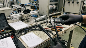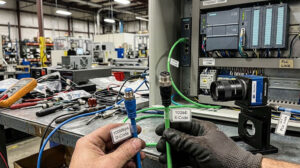
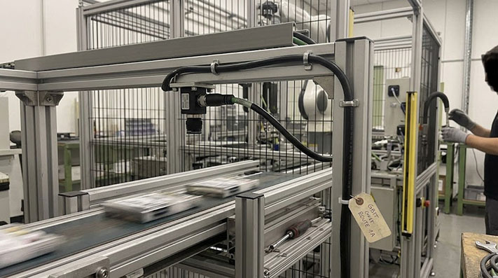
When a machine vision camera drops frames or intermittently loses its link on the factory floor, the culprit is rarely the camera sensor or the frame grabber. More often, it is a physical layer failure.
Standard RJ45 Ethernet cables designed for climate-controlled office spaces cannot withstand the mechanical stress, electromagnetic interference (EMI), temperature fluctuations, and oil exposure typical of automated production lines. For industrial GigE Vision systems, the M12 X-Code 8-pin connector has become the standard interface.
To choose the correct M12 X-Code cable assembly, system integrators and automation buyers must evaluate four technical factors: camera bandwidth, cable length limitations, thermal performance, and mechanical locking mechanisms.
Bandwidth Requirements for Common Camera Resolutions and Frame Rates
A GigE Vision camera transmits uncompressed image data to a host PC or industrial controller. This requires continuous, high-throughput bandwidth. If the cable assembly cannot reliably support the data rate, packet loss occurs, resulting in incomplete image frames or software timeouts.
To determine if a standard 1 Gbps M12 X-Code Ethernet cable is sufficient for your application, calculate the camera's raw data output using this formula:
$$ ext{Data Rate (Mbps)} = ext{Horizontal Pixels} imes ext{Vertical Pixels} imes ext{Frame Rate (fps)} imes ext{Color Depth (bits/pixel)} imes 10^{-6}$$
Because Ethernet protocol overhead accounts for roughly 15% to 20% of total bandwidth, the practical limit for a 1 Gbps physical link is approximately 800 to 850 Mbps of raw image data.
| Camera Resolution | Sensor Pixels | Frame Rate (fps) | Color Depth | Raw Data Rate (Mbps) | 1 Gbps M12 X-Code Suitability |
|---|---|---|---|---|---|
| VGA | 640 x 480 | 120 | 8-bit Mono | 294.9 | Fully Compatible (Low Load) |
| 2 Megapixel (FHD) | 1920 x 1080 | 30 | 8-bit Mono | 497.6 | Fully Compatible |
| 5 Megapixel | 2448 x 2048 | 15 | 8-bit Mono | 601.5 | Fully Compatible |
| 5 Megapixel | 2448 x 2048 | 25 | 12-bit Color | 1,504.0 | Exceeds 1 Gbps (Requires 10 Gbps link or compression) |
| 12 Megapixel | 4096 x 3000 | 10 | 8-bit Mono | 983.0 | Borderline (Requires 10 Gbps or frame rate reduction) |
For resolutions and frame rates that push near or beyond the 800 Mbps threshold, using an M12 X-Code cable configured for Cat6a (supporting up to 10 Gbps) is necessary to ensure headroom and prevent transmission bottlenecks.
Physical Layer Signal Integrity & Channel Specifications (M12 X-Code vs. RJ45)
Compliant with IEC 61076-2-109 and ANSI/TIA-568.2-D Cat6a standards. The 4-pair cross-shielding (X-Keying) isolates each pair to prevent alien crosstalk at high frequencies:
| Electrical & Signal Parameter | Standard Industrial Shielded RJ45 | M12 X-Code (8-Pin, Male/Female) | Engineering Impact on Vision Systems |
|---|---|---|---|
| Transmission Bandwidth Category | Cat6 (Up to 250 MHz) | Cat6a (Up to 500 MHz / 10 Gbps) | Prevents packet loss in multi-GigE (2.5G/5G/10G) cameras |
| Near-End Crosstalk (NEXT at 500 MHz) | ≥ 34.0 dB | ≥ 43.8 dB (X-Shield Isolation) | Eliminates intra-cable signal corruption between color channels |
| Return Loss (RL at 500 MHz) | ≥ 8.0 dB | ≥ 14.0 dB | Minimizes signal reflection over long stranded-conductor runs |
| Insertion Loss (Attenuation / 100m) | ~45.3 dB | ≤ 38.2 dB (Solid) / ≤ 49.5 dB (26 AWG Stranded) | Defines maximum achievable cable run without signal repeaters |
| Characteristic Impedance | 100 Ω ± 15% | 100 Ω ± 5% (Precision Machined) | Maintains clean eye-diagram in high-frame-rate GigE Vision |
Cable Length Limits at 1Gbps: When You Need a Switch
The IEEE 802.3 standard limits copper-based Ethernet channels to a maximum length of 100 meters. However, in industrial machine vision environments, this limit is often significantly shorter due to physical cable construction.
Solid vs. Stranded Conductors
Structured building cabling uses solid-core conductors, which offer low attenuation over long distances. Machine vision systems, however, often require cables routed through cable tracks, robotic arms, or tight enclosures. These high-flex applications require stranded conductors to prevent the copper from snapping under repetitive bending.
Stranded conductors have higher attenuation (signal loss) than solid copper of the same gauge. A high-flex Cat6a cable with 26 AWG or 28 AWG stranded wires may have a maximum reliable transmission distance of only 50 to 75 meters before signal degradation leads to bit errors.
Conductor Gauge (AWG), Stranding, and Maximum Transmission Distance Limits
Increasing stranded wire flex-life inherently increases signal attenuation. Use these maximum distance thresholds for 1 Gbps (GigE Vision) and 10 Gbps (10GigE Vision) links:
| Conductor Structure & AWG | Conductor DC Resistance (at 20°C) | Cable Outer Diameter (OD) | Max. Distance @ 1 Gbps (Cat6a) | Max. Distance @ 10 Gbps (Cat6a) | Recommended Installation Profile |
|---|---|---|---|---|---|
| 24 AWG Solid Copper | ≤ 93.8 Ω/km | 6.8 mm – 7.5 mm | 100.0 Meters (IEEE Limit) | 100.0 Meters | Static cable trays, long backbone runs |
| 26 AWG Stranded (7-strand) | ≤ 142.0 Ω/km | 6.0 mm – 6.5 mm | 75.0 Meters | 55.0 Meters | Medium-flex machine chassis, short patch runs |
| 26 AWG High-Flex (19-strand) | ≤ 145.0 Ω/km | 6.2 mm – 6.8 mm | 60.0 Meters | 40.0 Meters | Dynamic drag chains, high-speed gantry heads |
| 28 AWG Ultra-Flex (19-strand) | ≤ 223.0 Ω/km | 4.8 mm – 5.4 mm | 40.0 Meters | 25.0 Meters | Compact robotic wrists, tight space vision cells |
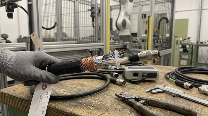
Mitigation Strategies
If your camera-to-controller distance exceeds 60 meters and you are using highly flexible, stranded-conductor cables, do not attempt to run a single continuous cable. Instead:
- Insert an Industrial Ethernet Switch: Place an unmanaged, DIN-rail mounted industrial switch closer to the camera to act as a signal repeater.
- Use Hybrid Cabling: Run solid-core bulk Ethernet cable for the long, static portions of the run (e.g., inside cable trays), and transition to a shorter, high-flex M12-to-RJ45 patch cable for the final, moving connection to the camera.
Industrial Temperature Range: Why Office Cat6 Fails
Standard office patch cables typically feature polyvinyl chloride (PVC) jackets rated for temperatures between 0°C and 50°C. When deployed on a factory floor, these cables fail for two thermal reasons:
Cold Embrittlement
In unheated warehouses, outdoor installations, or cold-storage packaging facilities, temperatures can drop below freezing. At these temperatures, standard PVC jackets lose their elasticity and become brittle. Any mechanical movement, vibration, or impact can crack the jacket, exposing the internal shielding and twisted pairs to moisture, dust, and electrical shorts.
Thermal Attenuation Drift
As the ambient temperature rises—often occurring near injection molding machines, industrial ovens, or poorly ventilated machine enclosures—the electrical resistance of the copper conductors increases. This causes signal attenuation to rise.
A cable run that passes signal integrity tests at 20°C may experience packet loss and connection drops when the ambient temperature reaches 60°C. Industrial-grade cable jackets made of Polyurethane (PUR) or Thermoplastic Elastomer (TPE) maintain their electrical performance and physical flexibility across a wider range (typically -40°C to 80°C).
Mechanical Motion Profiles, Bend Radius, and Flexing Cycles
Connecting vision cameras on high-speed industrial motion platforms requires strict adherence to dynamic mechanical limits to prevent inner conductor shear:
| Mechanical Motion Parameter | Static / Fixed Wiring | Continuous Drag Chain Flexing | High-Speed Robotic Torsion | Extreme Washdown / Cold Storage |
|---|---|---|---|---|
| Min. Bend Radius (PUR Jacket) | 5 × Cable OD | 10 × Cable OD | 12 × Cable OD | 8 × Cable OD |
| Max. Acceleration Rate | N/A | 50 m/s² (5G) | 30 m/s² | N/A |
| Max. Traversing Velocity | N/A | 300 m/min (5 m/s) | 180 m/min | N/A |
| Torsional Resistance Rating | N/A | ±90°/m | ±360°/m (100,000 cycles) | N/A |
| Flexing Life Cycles (PUR Outer) | N/A | > 5,000,000 to 10,000,000 cycles | > 3,000,000 cycles | -40°C Low-temp flex tested |
Connector Locking Mechanisms: Preventing Vibration Disconnects
An RJ45 plastic latch is designed for static office desks. In a factory environment characterized by continuous motor vibration, pneumatic actuator shock, and rapid gantry movement, the plastic tab of an RJ45 connector will eventually fatigue, loosen, or snap entirely. Even a microscopic shift in the contact alignment can cause a momentary loss of link, aborting the inspection cycle.
The M12 X-Code Advantage
The M12 X-Code connector resolves this mechanical vulnerability by using a screw-locking coupling nut.
- Screw-Locking (M12 x 1 Thread): Once threaded onto the camera's receptacle and torqued correctly (typically 0.6 Nm), the metal-to-metal connection prevents any axial or radial movement. This eliminates contact fretting and micro-interruptions.
- IP Ingress Protection: M12 connectors provide a dust-tight, washdown-resistant seal (often IP67), protecting the delicate electrical pins from cutting oils, coolants, and moisture that would quickly corrode an exposed RJ45 connection.
- 360-Degree Shielding: The metal housing of the M12 connector terminates the cable’s braided shield directly to the camera chassis, providing continuous path grounding to block electromagnetic interference from nearby motors and variable frequency drives (VFDs).
Shielding Topologies, Optical Coverage, and Electromagnetic Immunity (EMC)
High-power variable frequency drives (VFDs) and welding robots generate intense field interference. X-Code cables utilize individual pair shielding plus overall braiding:
| Shielding Architecture | Shield Construction Details | Braid Coverage (%) | EMC Attenuation (30 MHz – 1 GHz) | Transfer Impedance (Zt at 10 MHz) | Resistance to Industrial Interference |
|---|---|---|---|---|---|
| S/FTP (Individual Pair Foil + Braid) | Each pair Al-Foil + 360° Tinned Copper Braid | ≥ 85% Braid Coverage | ≥ 65 dB (Class FA) | ≤ 5.0 mΩ/m | Exceptional (Protects 10G signals next to servo motors) |
| SF/UTP (Overall Foil + Braid) | Al-Mylar Foil + Overall Tinned Copper Braid | ≥ 80% Braid Coverage | ~50 dB – 55 dB | ≤ 15.0 mΩ/m | High (Standard industrial Ethernet runs) |
| F/UTP (Overall Foil Only) | Single Al-Mylar Foil wrap with drain wire | 0% Braid Coverage | ~30 dB | ≤ 100.0 mΩ/m | Moderate (Static control panels only; poor flex fatigue) |
Coupling Nut Materials, Installation Torque, and IP Protection Ratings
To ensure gastight O-ring compression and prevent loosening under 10G mechanical vibration, follow these mechanical fastening specifications:
| Fastening / Sealing Parameter | Nickel-Plated Brass Coupling Nut | Stainless Steel Nut (316L / Food-Grade) | Anodized Aluminum Nut |
|---|---|---|---|
| Recommended Locking Torque | 0.6 Nm (Use calibrated M12 torque wrench) | 0.6 Nm – 0.8 Nm | 0.4 Nm – 0.5 Nm |
| Anti-Vibration Mechanism | Internal ratchet anti-loosening locking ring | Internal ratchet anti-loosening locking ring | Friction knurl thread |
| IP Ingress Protection (Mated) | IP67 / IP68 (2 meters / 24 hours) | IP69K (High-pressure 100 bar washdown at 80°C) | IP65 / IP67 |
| Internal O-Ring Material | NBR (Nitrile Rubber) | FKM (Viton) Fluorocarbon | NBR |
| Vibration Test Compliance | IEC 60068-2-6 (10 Hz – 2,000 Hz at 20g) | IEC 60068-2-6 / Salt Spray (96h) | IEC 60068-2-6 |
Checklist: Information to Gather Before Placing an RFQ
When sourcing M12 X-Code Gigabit Ethernet cables for your vision system, collecting specific application details beforehand prevents configuration errors and speeds up the sourcing process. Prepare the following details for your RFQ:
- Camera Specifications: Manufacturer, model, port type (direct M12 X-Code or RJ45), sensor resolution, and operating frame rate.
- Physical Interface:
- Connector A (e.g., M12 8-Pin X-Code Male, Straight or Right-Angle)
- Connector B (e.g., RJ45 Shielded, M12 X-Code, or flying leads)
- Installation Environment: Exposure to oil, water, or industrial chemicals; continuous motion/drag-chain requirements (specify flex cycles); and minimum/maximum ambient temperatures.
- Cable Length: Exact run length needed (including routing slack).
- Compliance Requirements: Specify if your system requires specific fire-retardant jacket ratings (e.g., halogen-free, flame-retardant PUR) or regional standards compliance.
Configure Your Vision Cabling with ConnecLink
Building a reliable machine vision system requires cables matched to your specific operational environment. ConnecLink, a brand of Tianlun Interconnect, provides a complete range of industrial Ethernet assemblies, including M12 X-Code 8-pin high-speed Gigabit Ethernet cables, D-coded variants, and custom hybrid assemblies.
To get a precise specification and quote for your next deployment, contact our technical team with your camera models, resolution requirements, and cable run lengths. We will spec the correct cable configuration to keep your inspection lines running without dropped frames.