
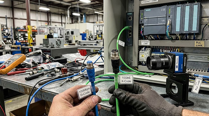
With M12 X-Code connectors offering Gigabit speeds, many automation engineers and equipment builders wonder if the older M12 D-Code standard is still a viable choice. Specifying a 100 Mbps connector might feel like a step backward, but for a wide range of industrial applications, D-Code is not only sufficient—it's often the most practical and cost-effective solution.
The decision between D-Code and X-Code isn't about choosing "old" versus "new" technology. It's about matching the cable specification to the actual data requirements of your device. Over-specifying network hardware can needlessly increase costs and complexity, while right-sizing your components frees up the budget for other critical parts of your design.
TL;DR: When to Use M12 D-Code
M12 D-Code is the ideal choice for any Industrial Ethernet device that operates at 100 Mbps or less. This includes the majority of PLCs, HMIs, standard sensors, and I/O blocks on the factory floor. Use D-Code for these end-point devices to optimize costs and reserve higher-speed, more expensive X-Code cables for network backbones or high-bandwidth equipment like machine vision cameras.
Key Differences: D-Code vs. X-Code
The primary distinction between M12 D-Code and X-Code lies in their pin count, internal construction, and resulting data rate capabilities.

| Feature | M12 D-Code (4-Pin) | M12 X-Code (8-Pin) |
|---|---|---|
| Data Rate | Up to 100 Mbps (Fast Ethernet) | Up to 10 Gbps (Gigabit Ethernet) |
| Wire Pairs | 2 pairs (4 conductors) | 4 pairs (8 conductors) |
| Shielding | Overall foil or braid shield | Overall shield plus internal shielding between pairs |
| Primary Use | End-point devices: sensors, PLCs, HMIs, I/O blocks | High-bandwidth devices: vision systems, network backbones |
| Cost | Generally more cost-effective | Higher cost due to more complex construction |
The 4-pin construction of D-Code is perfectly matched to the requirements of 10/100BASE-T Ethernet, which uses two pairs of wires—one for transmitting and one for receiving. X-Code's 8-pin design with enhanced internal shielding is necessary to prevent crosstalk between its four wire pairs, enabling the higher data throughput of Gigabit Ethernet.
Physical Layer Signal Integrity & Electrical Parameter Matrix (100m Channel)
Industrial Ethernet protocols (Profinet Type B/C, EtherCAT, EtherNet/IP) strictly mandate physical layer signal integrity to prevent packet loss and CRC errors under noisy EMI conditions:
| High-Frequency Electrical Parameter | M12 D-Code (Cat5e / 100BASE-TX) | M12 X-Code (Cat6A / 10GBASE-T) | Engineering Threshold & Impact |
|---|---|---|---|
| Operating Channel Frequency | 100 MHz | 500 MHz | Defines available signal throughput bandwidth |
| Differential Characteristic Impedance ($Z_0$) | 100 Ω ± 5% (at 100 MHz) | 100 Ω ± 5% (at 500 MHz) | Prevents signal reflection & impedance mismatching |
| Max. Insertion Loss / Attenuation | ≤ 22.0 dB / 100m (at 100 MHz) | ≤ 49.3 dB / 100m (at 500 MHz) | Signal level decay limit over max channel distance |
| Min. Pair-to-Pair NEXT (Near-End Crosstalk) | ≥ 35.3 dB (at 100 MHz) | ≥ 62.1 dB (at 500 MHz) | Prevents inductive coupling crosstalk between wire pairs |
| Min. Return Loss ($RL$) | ≥ 20.1 dB (at 100 MHz) | ≥ 17.3 dB (at 500 MHz) | Prevents signal echo caused by connector/cable mismatch |
| Max. Propagation Delay Skew | ≤ 45 ns / 100m | ≤ 25 ns / 100m | Crucial for ultra-precise motion synchronization (IEEE 1588) |
Where 100 Mbps Is Still the Right Speed
While Gigabit Ethernet is essential for some applications, many common automation devices generate nowhere near that much data. Using an X-Code cable for a device that only needs 5 Mbps is like using a fire hose to water a houseplant.
M12 D-Code is the appropriate, professional choice for connecting:
- PLCs and Controllers: Most PLC communication and programming traffic falls well within the 100 Mbps limit.
- HMIs (Human-Machine Interfaces): Standard operator panels that display process data, trends, and alarms do not require Gigabit speeds.
- Remote I/O Blocks: Modules that consolidate signals from multiple standard sensors and actuators rarely saturate a 100 Mbps link.
- Standard Sensors and Actuators: Photoelectric sensors, proximity switches, and solenoid valve manifolds with Ethernet/IP, Profinet, or EtherCAT interfaces.
- Barcode Scanners and RFID Readers: The data packets from these identification devices are small and infrequent.
For these applications, a D-coded cable delivers reliable performance without the added expense of an over-specified X-coded assembly.
Industrial Ethernet Protocol Specification & Cabling Standards
Different industrial bus organizations (PI, ETG, ODVA) define precise cable topologies and color codes for 100 Mbps D-Coded interconnects:
| Industrial Protocol / Standard | Wire Pair Topology | Conductor Gauge & Construction | Industry Standard Wire Color Code | Recommended M12 D-Code Cable Type |
|---|---|---|---|---|
| Profinet (PI Standard) | Star-Quad (4 cores twisted together) | 22 AWG / 7-strand or 19-strand | Pin 1: Yellow (TD+), Pin 2: White (RD+), Pin 3: Orange (TD-), Pin 4: Blue (RD-) | Profinet Type A (Fixed), Type B (Flex), Type C (Drag Chain) |
| EtherCAT (ETG.1000) | 2 Twisted Pairs or Star-Quad | 22 AWG or 24 AWG | Pin 1: Yellow (TX+), Pin 2: White (RX+), Pin 3: Orange (TX-), Pin 4: Blue (RX-) | 100 Fast Ethernet Shielded Twisted Pair (STP) |
| EtherNet/IP (ODVA) | 2 Twisted Pairs (UTP/STP) | 24 AWG Solid or Stranded | Pin 1: White/Orange (TX+), Pin 2: White/Green (RX+), Pin 3: Orange (TX-), Pin 4: Green (RX-) | Category 5e T568B Standard Industrial Pair Cable |
| CC-Link IE Field Basic | 2 Twisted Pairs | 24 AWG Stranded | Standard T568A / T568B Industrial Ethernet | Shielded Cat5e Industrial Cable |
Dynamic Mechanical Endurance for Drag Chain and Robotic Motion
M12 D-Code cables deployed in moving cable carriers or multi-axis articulated robots require specialized conductor stranding profiles to prevent conductor metal fatigue:
| Motion Profile / Test Mode | Min. Bending Radius Factor | Conductor Stranding Spec (IEC 60228) | Tested Flexing / Torsional Life Cycles | Max. Acceleration ($a_{text{max}}$) | Max. Traverse Speed ($v_{text{max}}$) |
|---|---|---|---|---|---|
| Static Cabinet / Fixed Routing | 5 × Cable OD | Class 5 Bare Copper (Solid/Stranded) | N/A | N/A | N/A |
| Continuous Drag Chain (Profinet Type C) | 7.5 × Cable OD | Class 6 Extra-Fine Tinned Copper | ≥ 5,000,000 Cycles | 10 m/s² | 180 m/min |
| High-Speed Long-Travel Drag Chain | 10 × Cable OD | Ultra-Fine Bundled Strands (Ø ≤0.08mm) | ≥ 10,000,000 Cycles | 50 m/s² | 300 m/min |
| Robotic Torsional Motion (3D) | 12 × Cable OD | Special Center Core Strain-Relief Stranding | ≥ 3,000,000 Cycles (at ±180°/m) | 20 m/s² | 180°/sec Angular Velocity |
Mixing D-Code and X-Code on the Same Network
A common concern for system integrators is whether using D-Code cables will "slow down" a modern Gigabit network. The answer is no—at least, not in the way you might think.
Modern industrial switches are built for this exact scenario. When you connect a 100 Mbps device using a D-Code cable to a Gigabit switch, the switch port will automatically negotiate its speed down to 100 Mbps for that specific connection. The rest of the switch ports connected to Gigabit devices will continue to operate at full speed.
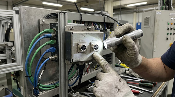
This allows for a highly efficient and cost-effective network architecture:
- Backbone: Use M12 X-Code cables to link your main industrial switches, ensuring a high-speed data highway for all network traffic.
- End-Point Devices: Use M12 D-Code cables to connect individual sensors, PLCs, and other 100 Mbps devices to the switches.
This hybrid approach ensures that bandwidth is available where it's needed (for high-resolution cameras or server connections) while saving money on the dozens of connections that don't require it.
Industrial Jacket Materials & EMC Shielding Efficiency Matrix
Selecting the proper outer jacket (PVC, PUR, TPE) and EMI shielding structure prevents cable degrading from cutting fluids and high-frequency noise generated by VFDs:
| Outer Jacket & Shield Topology | Operating Temperature | Resistance to CNC Coolants & Cutting Oils | Halogen-Free & Flame Retardancy | Transfer Impedance ($Z_t$ at 10 MHz) | Shielding Attenuation (30 MHz – 1 GHz) | Target Installation Environment |
|---|---|---|---|---|---|---|
| PVC / SF/UTP (Foil + Braid) | -20°C to +80°C | Poor (Swells/Cracks) | Flame Retardant (UL VW-1) | ≤ 50 mΩ/m | ~40 dB – 50 dB | Low-cost static control cabinets, standard IP20/IP67 dry areas |
| PUR / SF/UTP (Profinet Type C) | -40°C to +90°C | Superior (DIN EN 60811-404) | Zero Halogen (IEC 60754-1 / IEC 60332-1) | ≤ 10 mΩ/m | ~60 dB – 75 dB | Harsh CNC machining centers, dynamic drag chains with heavy oil |
| TPE / SF/UTP High-Temp Spec | -40°C to +105°C | Exceptional (Chemical/UV) | Flame Retardant (UL 1581 FT-1) | ≤ 5 mΩ/m | ≥ 80 dB (High Noise) | Extreme ambient outdoor environments, welding cells, heavy EMI areas |
Plan for Performance, Not for Hypotheticals
Choosing M12 D-Code for 100 Mbps devices is a sound engineering decision, not a compromise. An upgrade to Gigabit Ethernet involves more than just swapping a cable; it requires that the devices on both ends of the cable—and the switch port—are all Gigabit-capable and equipped with X-Code receptacles. If your current PLC or sensor only has a 100 Mbps D-Code port, you are not losing any performance by using a D-Code cable.
By carefully matching your connector and cable specifications to your device requirements, you can build a reliable and robust industrial network that meets both performance benchmarks and budget targets.
Need Help Optimizing Your Industrial Network Cables?
A budget-conscious project requires smart component choices. If you're deciding between D-Code and X-Code for your application, we can help.
Tell us about your network devices, required data rates, and installation environment. The ConnecLink team can help you configure the right M12 cable assemblies to optimize costs without sacrificing performance. Provide a drawing, existing part number, or your list of requirements to get a clear and competitive RFQ.