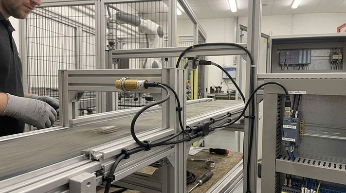
In many automated systems, a single sensor event needs to trigger actions in two different places[cite: 16]. For example, a proximity sensor might need to inform a local machine controller to stop a process while also sending its status to a central plant monitoring system[cite: 16]. An M8 Y-splitter cable seems like a simple hardware solution for this, but success depends entirely on the electrical configuration[cite: 16].
Using an M8 Y-splitter to send one sensor signal to two separate PLC or controller inputs is a common and effective technique, provided you follow one critical rule: both PLC inputs must be electrically compatible with the sensor’s output type[cite: 16]. In short, if your sensor is a PNP type, both inputs must be sinking[cite: 16]. If your sensor is NPN, both inputs must be sourcing[cite: 16].
How a Y-Splitter Duplicates a Signal
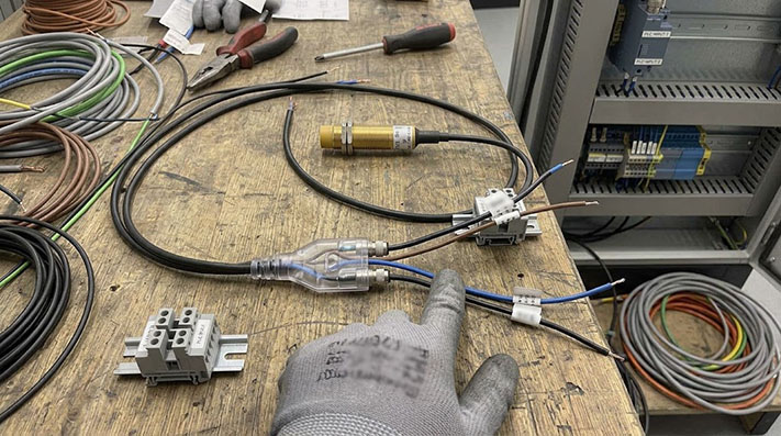
A standard 3-wire M8 sensor uses three connections: Power (V+), Ground (0V), and Signal[cite: 16]. A Y-splitter cable assembly is designed to distribute these connections simply and efficiently[cite: 16].
The splitter’s main trunk connects to the sensor[cite: 16]. Inside the molded "Y" junction, the wiring is split[cite: 16]:
- The Power wire from the sensor is connected to the power pin on both output branches[cite: 16].
- The Ground wire from the sensor is connected to the ground pin on both output branches[cite: 16].
- The Signal wire from the sensor is connected to the signal pin on both output branches[cite: 16].
This creates two identical outputs from one input source[cite: 16]. While mechanically simple, the electrical implications are significant[cite: 16].
 [cite: 16]
The Critical Step: Matching Sensor Output to PLC Inputs
The most common point of failure when using a Y-splitter is a mismatch between the sensor's output logic and the PLC's input logic[cite: 16]. Industrial sensors and PLC inputs typically use either PNP (sourcing) or NPN (sinking) configurations[cite: 16].
PNP (Sourcing) vs. NPN (Sinking) Logic
- PNP Sensor (Sourcing): When activated, a PNP sensor sources current, meaning it provides a positive voltage (+24V, for example) on its signal wire[cite: 16]. The corresponding PLC input must be a sinking type, which completes the circuit by connecting the signal line to ground internally[cite: 16].
- NPN Sensor (Sinking): When activated, an NPN sensor sinks current, meaning it connects its signal wire to ground (0V)[cite: 16]. The corresponding PLC input must be a sourcing type, which provides a small positive voltage that the sensor then pulls to ground to register the signal[cite: 16].
Electrical Compatibility & Load Paralleling Parameters
When splitting a signal across two inputs, the sensor's output transistor must drive both input circuits simultaneously without incurring unacceptable voltage drops or exceeding thermal limits:
| Sensor / Logic Architecture | Compatible PLC Input Type (Both Branches) | Max. Leakage Current (Off-State) | Equivalent Input Resistance (IEC 61131-2 Type 3) | Drive Current Margin ($I_{text{sensor_max}}$) | Signal Integrity Risk under Paralleled Load |
|---|---|---|---|---|---|
| PNP Output (Sourcing) | Sinking Input (Signal pulled to 0V) | ≤ 1.5 mA | ~3.0 kΩ (Per Input Branch) | ≥ 100 mA (Must support combined PLC current) | Voltage drop ($V{text{drop}} le 1.2text{V}$) under double load ($I{text{total}} approx 14text{mA}$). |
| NPN Output (Sinking) | Sourcing Input (Signal pulled to +24V) | ≤ 1.0 mA | ~3.0 kΩ (Per Input Branch) | ≥ 100 mA | Low-level output voltage ($V_{text{OL}}$) floating above 3.0V threshold. |
| Push-Pull (HTL/TTL) | Sinking or Sourcing | ≤ 0.5 mA | 1.5 kΩ – 10 kΩ | ≥ 200 mA | High-speed edge ringing due to un-terminated line reflections. |
| Mismatched (PNP + NPN) | Incompatible | N/A | Direct short-circuit risk | N/A | Cross-feed current destroys sensor output transistor. |
The Compatibility Rule for Y-Splitters
Because the Y-splitter connects the single sensor signal wire to both PLC inputs, both of those inputs must be designed to receive the same type of signal[cite: 16].
- If you use a PNP sensor (sourcing): Both PLC inputs must be sinking types[cite: 16].
- If you use an NPN sensor (sinking): Both PLC inputs must be sourcing types[cite: 16].
Attempting to connect a single sensor to two different input types (one sinking, one sourcing) will not work[cite: 16]. The mismatched input will either fail to register the signal, register it unreliably, or potentially interfere with the correctly matched input[cite: 16]. Always check the hardware documentation for your sensor and both PLC input modules before installation[cite: 16].
Practical Considerations for Your Setup
Before deploying Y-splitters in active production environments, verify the mechanical sealing and electrical specifications to prevent intermittent connection faults[cite: 16].
M8 Connector Mechanical Specs, Locking Torques & Environmental Ratings
Over-tightening or under-tightening M8 connectors can destroy O-rings or cause intermittent pin resistance under vibration:
| Mechanical / Physical Parameter | M8 3-Pin Screw Locking (A-Coded) | M8 4-Pin Screw Locking (A-Coded) | M8 Snap-in Quick Locking | Testing Standard |
|---|---|---|---|---|
| Pin / Contact Diameter | 1.0 mm (Gold-plated Brass) | 0.8 mm (Gold-plated Brass) | 1.0 mm / 0.8 mm | IEC 61076-2-104 |
| Rated Current per Contact | 4.0 Amps | 3.0 Amps | 3.0 Amps – 4.0 Amps | IEC 60512-5-2 |
| Rated Voltage | 60 V AC / 75 V DC | 30 V AC / 30 V DC | 30 V AC / 60 V DC | IEC 60664-1 |
| Recommended Tightening Torque | 0.4 Nm (Steel Coupling Nut) | 0.4 Nm (Steel Coupling Nut) | Manual Push-Pull | Torque Wrench Standard |
| Contact Resistance | ≤ 10 mΩ | ≤ 10 mΩ | ≤ 15 mΩ | IEC 60512-2-1 |
| Ingress Protection (Mated) | IP67 / IP68 (1m / 24h) | IP67 / IP68 (1m / 24h) | IP65 | IEC 60529 |
Diagnostic LEDs on Each Branch
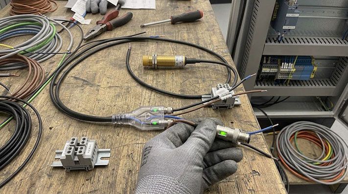
Some M8 Y-splitters are available with integrated LED indicators on each of the branch connectors[cite: 16]. This is a valuable feature for commissioning and troubleshooting[cite: 16]. An LED on each leg provides immediate visual confirmation that the signal from the sensor is successfully reaching each PLC input, helping technicians isolate connection problems quickly without needing a multimeter[cite: 16].
 [cite: 16]
Cable Length and Signal Skew
For most standard-speed digital sensor applications (like proximity or photoelectric sensors), minor differences in the length of the "Y" legs are not a concern[cite: 16]. The splitter is molded as a single unit, and the internal lengths are functionally identical[cite: 16]. However, if you are using a splitter in a system with very high-speed signals or extending one branch with another cable, it is best practice to keep the total cable length to each PLC as similar as possible to avoid signal timing differences[cite: 16].
High-Speed Signal Propagation & Cable Length Asymmetry Limits
Excessive length differences ($Delta L$) between splitter legs introduce signal propagation delay and capacitive loading issues for high-frequency switching:
| Application Speed / Sensor Type | Max. Frequency ($f_{text{max}}$) | Permissible Branch Length Asymmetrical Delta ($Delta L$) | Cable Propagation Delay ($tau_pd$) | Mutual Capacitance Limit (Core-to-Core) | Signal Skew ($Delta t_{text{skew}}$) Limit |
|---|---|---|---|---|---|
| Standard Proximity (Inductive) | ≤ 1.0 kHz | ≤ 10.0 meters | ~5.0 ns / meter | ≤ 120 pF / meter | Negligible (< 50 ns) |
| High-Speed Optical / Photoelectric | ≤ 25.0 kHz | ≤ 2.0 meters | ~5.0 ns / meter | ≤ 80 pF / meter | ≤ 10 ns |
| High-Speed Counter / Encoder Pulse | ≤ 200.0 kHz | ≤ 0.3 meters | ~4.8 ns / meter | ≤ 50 pF / meter (Low Cap) | ≤ 1.5 ns (Strict Matching Required) |
When is a Y-Splitter NOT the Right Solution?
While useful, a simple Y-splitter isn't a universal solution[cite: 16]. It may not be appropriate if:
- You need to connect a PNP sensor to an NPN input[cite: 16]. A splitter cannot convert the signal type; you would need a dedicated signal conditioning module[cite: 16].
- The two destination systems require complete electrical isolation[cite: 16]. A Y-splitter shares a common power and ground connection between all three ports[cite: 16].
- The application involves a safety-rated circuit[cite: 16]. Safety circuits have specific requirements for redundancy and monitoring that a standard Y-splitter is not designed to meet[cite: 16].
Hardware Selection Matrix: Passive Y-Splitter vs. Active Signal Isolator
Evaluate whether a passive cable assembly or an active DIN-rail signal splitter is necessary for your system architecture:
| Functional Criterion | Passive M8 Y-Splitter Assembly | Active Signal Splitter / Optocoupler Module | Dedicated PLC Signal Conditioning Relay |
|---|---|---|---|
| PNP to NPN Logic Conversion | Not Supported (Requires identical logic)[cite: 16] | Supported (Fully configurable) | Supported |
| Galvanic Isolation | None (Common GND and V+)[cite: 16] | Full Isolation (≥ 1.5 kV DC Port-to-Port) | Full Isolation (Electromechanical / Opto) |
| Response Time / Propagation Delay | < 1 ns (Direct Copper Connection) | 1.0 µs – 10 µs (Optocoupler delay) | 5 ms – 15 ms (Mechanical Contacts) |
| Installation Footprint | Direct In-Line / Molded Cable Mount[cite: 16] | DIN-Rail Mounted in Control Cabinet | DIN-Rail Mounted in Control Cabinet |
| Cost & Complexity Index | Low ($)[cite: 16] | Medium-High ($$$) | Medium ($$) |
Configuring the Right M8 Splitter Cable
Getting the configuration right is key to a reliable installation[cite: 16]. A correctly specified M8 Y-splitter provides a clean, durable, and error-free way to duplicate a sensor signal[cite: 16]. Using a pre-molded assembly is almost always more reliable than manually splicing wires in the field, especially in environments with vibration, moisture, or dust[cite: 16].
If your application requires a custom configuration—such as a 1-to-3 split, different connector types on each branch, or specific cable lengths—we can help design a solution[cite: 16]. When you request a quote, include a drawing or description of your setup, the sensor and PLC types if known, and the required quantities[cite: 16]. This information helps us ensure the final cable assembly matches your electrical and mechanical needs precisely[cite: 16].