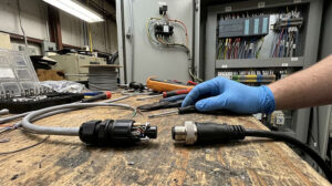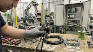
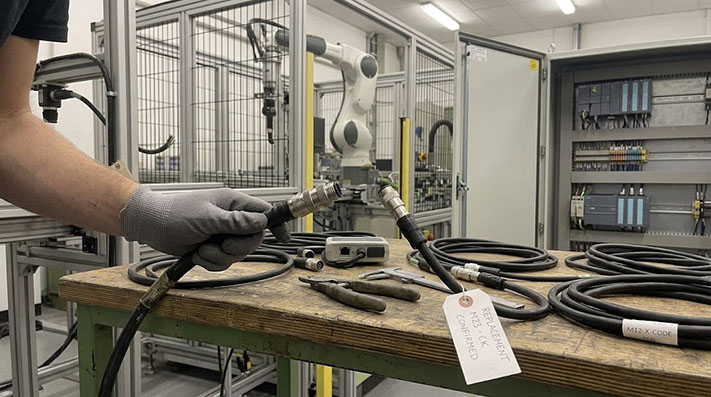
Sourcing replacement servo motor and encoder cables for systems from manufacturers like Siemens, Mitsubishi, or Fanuc presents a common dilemma for factory maintenance, repair, and operations (MRO) engineers and procurement teams[cite: 15]. Relying solely on OEM-branded replacement cables ensures compatibility, but it often comes with long lead times and high markups[cite: 15]. On the other hand, purchasing third-party equivalents can feel risky if the exact specifications of the original cable are not fully understood[cite: 15].
A successful transition to equivalent cable assemblies requires a clear understanding of the original equipment manufacturer (OEM) part number, distinguishing between rigid tolerances and flexible parameters, and evaluating critical engineering data[cite: 15].
Decoding the Specs Hidden in the OEM Part Number
An OEM servo cable part number is rarely a random sequence of characters[cite: 15]. It is typically a structured code that embeds critical electrical, mechanical, and material specifications[cite: 15].
For instance, in typical European and Asian servo systems, the alphanumeric characters in a cable’s model code represent a specific matrix of variables[cite: 15]:
- Application Class: Characters that indicate whether the cable is designed for fixed installation, basic bending, or high-flex drag-chain environments[cite: 15].
- Connector Configuration: Identifiers for the connector size (such as M23, M40, or proprietary rectangular plastic shells), angle (straight vs. 90-degree right angle), and locking mechanism (threaded vs. quick-lock designs like SpeedTec-compatible systems)[cite: 15].
- Conductor Layout: Codes detailing the number of power conductors, brake pairs, and shielding configurations (for example,
(4G1.5 + 2x2x0.75)Crepresenting four power conductors of 1.5 mm² plus two shielded pairs of 0.75 mm² for the brake/thermal sensor)[cite: 15]. - Jacket Material: Abbreviations indicating Polyvinyl Chloride (PVC), Polyurethane (PUR), or Thermoplastic Elastomer (TPE) jackets, which dictate chemical, oil, and flame resistance[cite: 15].
Physical & Chemical Performance Metrics for Cable Outer Jackets
Choosing the correct outer jacket material determines the operational lifespan of a replacement servo cable in hostile factory environments:
| Engineering Property | Polyvinyl Chloride (PVC) | Polyurethane (PUR) | Thermoplastic Elastomer (TPE) | Testing Standard |
|---|---|---|---|---|
| Shore Hardness (Outer Jacket) | A 80 – A 90 | A 90 – D 55 | A 85 – D 50 | ISO 868 / ASTM D2240 |
| Tensile Strength | 12 – 18 MPa | 35 – 55 MPa | 20 – 35 MPa | DIN EN ISO 527 |
| Tear Growth Resistance | ~15 N/mm | ≥ 40 N/mm | ≥ 30 N/mm | ISO 34-1 |
| Static Temp. Range | -20°C to +80°C | -40°C to +80°C | -50°C to +105°C | IEC 60811-507 |
| Dynamic Flex Temp. Range | -5°C to +60°C | -30°C to +80°C | -40°C to +90°C | EN 50396 |
| Coolant & Cutting Oil Resistance | Moderate (Short exposure) | Exceptional (ASTM Oil 1 & 2) | High (Bio-oils & Acids) | DIN EN 60811-404 |
| Flame Retardancy Rating | VW-1 / FT1 | IEC 60332-1-2 / FT2 | VW-1 / FT1 / FT2 | UL 1581 / UL 2556 |
Before sourcing an equivalent, a buyer must obtain or reconstruct the original cable’s structural datasheet[cite: 15]. Relying purely on the outer jacket print is risky, as the print often shows only the raw bulk cable standard (e.g., UL AWM styles) rather than the complete connectorized assembly configuration[cite: 15].
Cross-Reference Risks: What Must Match Exactly vs. What Has Tolerance
When cross-referencing an OEM cable to a third-party equivalent, treating every specification with equal weight can lead to over-specification (inflating costs) or under-specification (causing field failures)[cite: 15]. The following breakdown categorizes critical parameters by their required level of precision[cite: 15].
Absolute Matches (Zero Tolerance)
These parameters must align exactly with the OEM specification. Any deviation will prevent physical installation or cause immediate electrical failure[cite: 15]:
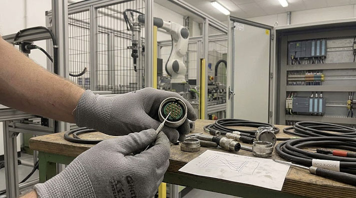
- Pinout Mapping and Contact Termination: The point-to-point wiring schematic from Connector A to Connector B must be identical[cite: 15]. A single misplaced contact on a feedback connector can destroy an encoder or cause a drive runaway condition[cite: 15].
- Connector Thread and Shell Type: An M23 thread must match the exact pitch of the motor-mount receptacle[cite: 15]. Quick-lock styles must be fully mating-compatible with the motor-side receptacle[cite: 15].
- Shielding Termination (360-Degree Continuity): For electromagnetic compatibility (EMC), the overall braided shield must terminate with 360-degree coverage inside the connector hood (typically via a grounding cone or shield crimp sleeve)[cite: 15]. Pigtail shield terminations are generally unacceptable for high-frequency PWM drive outputs[cite: 15].
Connector Shell Engineering Specs, Pin Ratings, and Mating Tolerances
Servo motor connectors must maintain IP seal integrity under harsh machine vibrations (up to 20g):
| Connector Series & Keying | Nominal Contact Current | Rated Voltage (IEC) | Mating Cycles (Durability) | Recommended Tightening Torque | Ingress Protection Rating (Mated) |
|---|---|---|---|---|---|
| M23 Signal (12-Pin / 17-Pin) | 7.0 A per pin | 160 V / 250 V | ≥ 500 Cycles | 0.8 Nm – 1.0 Nm | IP67 / IP68 |
| M23 Power (6-Pin 4+PE+1) | 28.0 A (Power) / 10.0 A (Brake) | 630 V (Power) / 250 V (Brake) | ≥ 500 Cycles | 1.2 Nm – 1.5 Nm | IP67 / IP68 |
| M40 Power (6-Pin 4+PE+1) | 75.0 A (Power) / 30.0 A (Brake) | 630 V (Power) / 250 V (Brake) | ≥ 500 Cycles | 3.0 Nm – 3.5 Nm | IP67 / IP68 |
| SpeedTec Quick-Lock Type | Same as threaded M23/M40 | Same as threaded M23/M40 | ≥ 500 Cycles | 1/8 Turn Click Lock | IP67 / IP69K (High Pressure) |
Conditional Matches (Application-Dependent)
These parameters depend heavily on how and where the machine operates[cite: 15]:
- Jacket Material & Motion Requirements: If the cable is routed in a dry, static cable tray, a standard PVC jacket is acceptable[cite: 15]. If it is routed inside a continuous-flex drag chain exposed to cutting oils or coolants, a high-grade PUR or TPE jacket with an appropriate minimum bend radius is required[cite: 15].
Dynamic Motion Profiles, Bend Radius Limits, and Mechanical Life Expectancy
To replace OEM drag-chain cables without causing inner conductor fatigue or sheath degradation, adhere to these dynamic thresholds:
| Motion Parameter | Fixed / Static Wiring | Standard Cable Tray Flexing | Continuous Drag-Chain Dynamic | High-Speed Robotic 3D Torsion |
|---|---|---|---|---|
| Min. Bend Radius (PUR / TPE) | 4.0 × Cable OD | 7.5 × Cable OD | 10.0 × Cable OD | 12.5 × Cable OD |
| Max. Acceleration Rate | N/A | ≤ 10 m/s² | 50 m/s² (5G Acceleration) | 80 m/s² (8G Acceleration) |
| Max. Traversing Speed | N/A | ≤ 120 m/min | 300 m/min (5 m/s) | 240 m/min |
| Torsional Resistance Limit | N/A | N/A | ±90° / meter | ±360° / meter (100,000 cycles) |
| Flexing Life Cycles (PUR Outer) | N/A | > 1,000,000 cycles | > 5,000,000 to 10,000,000 cycles | > 3,000,000 cycles (3D Flex) |
- Conductor Cross-Section (AWG/mm²): While the equivalent must meet or exceed the current-carrying capacity of the OEM cable, slight variances in copper stranding or wire gauge (e.g., substituting a metric 1.5 mm² with an equivalent AWG 16) are acceptable as long as voltage drop limits over the total cable length are not exceeded[cite: 15].
Power Conductor Specifications, Current Rating, and Voltage Drop Limits
Servo power lines carry pulse-width modulated (PWM) high-voltage currents. Replacement conductors must match or exceed these electrical thresholds (rated at 30°C ambient):
| Nominal Cross-Section | AWG Equivalent | Max. DC Resistance (at 20°C) | Max. Current Capacity (PUR 80°C) | Operating Voltage Rating (U0/U) | Continuous Grounding Conductor Gauge |
|---|---|---|---|---|---|
| 1.5 mm² | AWG 16 | ≤ 13.3 Ω/km | 18.0 Amps | 600 V / 1000 V | Same Gauge (1.5 mm² / Green-Yellow) |
| 2.5 mm² | AWG 14 | ≤ 7.98 Ω/km | 26.0 Amps | 600 V / 1000 V | Same Gauge (2.5 mm² / Green-Yellow) |
| 4.0 mm² | AWG 12 | ≤ 4.95 Ω/km | 34.0 Amps | 600 V / 1000 V | Same Gauge (4.0 mm² / Green-Yellow) |
| 6.0 mm² | AWG 10 | ≤ 3.30 Ω/km | 44.0 Amps | 600 V / 1000 V | Same Gauge (6.0 mm² / Green-Yellow) |
| 10.0 mm² | AWG 8 | ≤ 1.91 Ω/km | 61.0 Amps | 600 V / 1000 V | Same Gauge (10.0 mm² / Green-Yellow) |
Flexible Parameters (High Tolerance)
- Outer Jacket Color: While standard conventions exist (such as orange for power cables and green for feedback/encoder cables), jacket color has no impact on electrical or mechanical performance[cite: 15].
- Overmold Style: The physical shape of the strain relief or overmold may vary from the OEM design, provided it does not interfere with the physical clearances around the motor junction box[cite: 15].
| Parameter | Required Status | Risk of Mismatch |
|---|---|---|
| Pinout Mapping | Exact Match | Electrical damage, system fault, or motor runaway[cite: 15]. |
| Connector Mating | Exact Match | Inability to plug in or loss of IP ingress rating[cite: 15]. |
| Shielding Style | Exact Match | EMI noise, signal corruption, encoder faults[cite: 15]. |
| Jacket Material | Application-Dependent | Premature cable wear, cracking, or chemical breakdown[cite: 15]. |
| Jacket Color | Flexible | Cosmetic variance only[cite: 15]. |
Encoder Cable Compatibility: Absolute vs. Incremental Considerations
Encoder and feedback cables carry low-voltage high-frequency signals that are highly susceptible to electromagnetic interference (EMI)[cite: 15]. The choice of equivalent cable must account for the specific feedback technology used by the servo system[cite: 15].
 [cite: 15]
Incremental Encoders
Incremental encoders rely on quadrature signals (A, B, Z and their inverted complements) to determine position[cite: 15]. Because these signals are differential (RS-422 standard), the equivalent cable must use twisted-pair conductors[cite: 15].
If a third-party supplier builds a replacement cable using parallel, non-twisted conductors, the differential noise cancellation is lost[cite: 15]. This results in positioning drift and intermittent axis tracking errors, particularly over cable runs exceeding 5 meters[cite: 15].
Absolute Encoders (EnDat, BiSS, Hiperface, SSI)
Absolute encoders transmit precise position data via high-speed serial protocols[cite: 15]. These systems are sensitive to cable capacitance and signal attenuation[cite: 15]:
- Capacitance Limits: High-speed data lines require low-capacitance insulation materials (such as Polypropylene or Foamed Polyethylene rather than standard PVC)[cite: 15]. High cable capacitance distorts the digital pulse shapes, leading to cyclic redundancy check (CRC) errors on the drive[cite: 15].
- Dual-Shielding Requirements: Many absolute encoder systems require individually shielded pairs for the data lines in addition to an overall braided shield[cite: 15]. When sourcing an equivalent, verify that the inner shields are isolated from one another and terminated correctly at the connector pins according to the OEM print[cite: 15].
Encoder Cable Signal Integrity, Shielding Topologies, and Capacitance Limits
Feedback cables operate in high-EMI environments generated by neighboring servo drive power cables. High capacitance distorts high-speed serial pulses:
| Shielding Topology | Construction & Coverage | Mutual Capacitance (Core-to-Core) | Transfer Impedance (Zt at 10 MHz) | Typical Signal Protocol Compatibility |
|---|---|---|---|---|
| Double Shielded (S/FTP) | Individual Foil Pairs + ≥ 85% Tinned Braid | ≤ 55 pF/m (Low-Loss) | ≤ 5.0 mΩ/m | Absolute Encoders (EnDat 2.2, BiSS-C, DRIVE-CLiQ) |
| Overall Shielded (SF/UTP) | Al-Mylar Foil + ≥ 80% Tinned Braid | ≤ 75 pF/m | ≤ 15.0 mΩ/m | Incremental Encoders (RS-422 TTL / HTL) |
| Single Shielded (F/UTP) | Al-Mylar Foil wrap only (Static use) | ≤ 110 pF/m | ≤ 80.0 mΩ/m | Thermal Switch / Brake Pairs only |
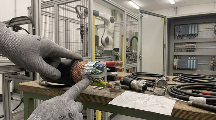 [cite: 15]
Third-Party Cable Warranty and Liability: What to Ask Your Supplier
When moving away from OEM-branded cables, the sourcing team must shift the burden of verification to the assembly supplier[cite: 15]. To mitigate risks associated with machine downtime and equipment damage, ask potential cable assembly suppliers the following questions before issuing a purchase order[cite: 15]:
- "How do you perform electrical testing on completed assemblies?"[cite: 15]
- The Right Answer: The supplier should conduct automated continuity, short-circuit, and high-pot (dielectric withstand voltage) testing on 100% of finished assemblies, rather than relying on random sample testing[cite: 15].
- "What brand of raw cable and connectors are used in the assembly?"[cite: 15]
- The Right Answer: The supplier should be transparent about their component sourcing, identifying UL-recognized raw cable and connector manufacturers that match the environmental ratings of the OEM parts[cite: 15].
- "What is the rated flex-life and minimum bend radius of the bulk cable?"[cite: 15]
- The Right Answer: For dynamic applications, the supplier must provide technical data sheets showing the cable has been tested to withstand a specific number of bending cycles (e.g., 5 million or 10 million cycles) at a defined bend radius[cite: 15].
- "Do you provide customized pinout configurations and custom tail treatments?"[cite: 15]
- The Right Answer: A capable technical partner should easily accommodate requests for custom flying-lead lengths, specific crimp terminals, or custom labeling to match your exact panel layout[cite: 15].
Technical RFQ Checklist for Custom Servo Cable Assemblies
To obtain an accurate, competitive quote for an equivalent servo motor or encoder cable assembly, compile the following details for your supplier[cite: 15]:
- OEM Reference: Original part numbers for the cable assembly and, if known, the specific servo motor and drive models[cite: 15].
- Connector Configurations: Specify Connector A and Connector B types (e.g., M23 6-pin female straight to flying leads with bootlace ferrules)[cite: 15].
- Cable Length: Exact tip-to-tip length needed for the application[cite: 15].
- Application Environment: Static installation, standard cable track (provide bend radius and speed requirements), or exposure to specific industrial oils and coolants[cite: 15].
- Target Standards: Clarify if the assembly requires specific jacket certifications (such as UL/CSA AWM styles) to comply with regional electrical codes[cite: 15].
Have an OEM Part Number?
ConnecLink, a brand of Tianlun Interconnect, specializes in configured industrial cable assemblies, including M23 heavy-duty servo motor and encoder cables[cite: 15].
If you have an OEM part number, drawing, or sample photo, send it over[cite: 15]. Our team will analyze the technical specifications and offer a high-performance equivalent with matching or superior materials tailored to your operating environment[cite: 15].