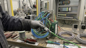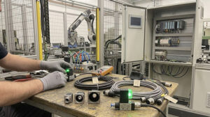
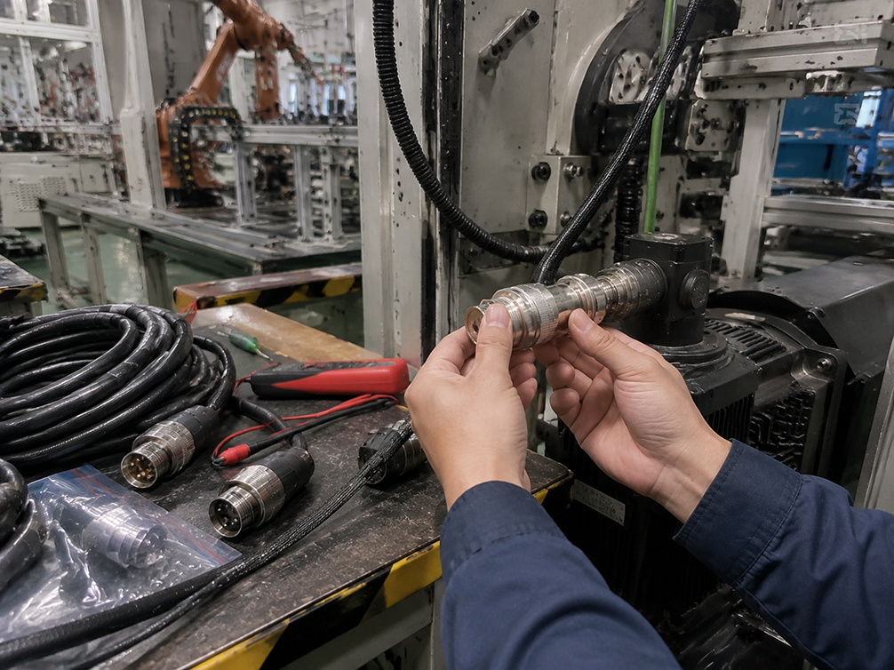
When a servo motor axis exhibits erratic behavior, maintenance teams often focus on tuning parameters, replacing the motor, or swapping the drive. However, a frequently overlooked cause is the M23 servo cable assembly itself. Inadequate or damaged shielding can allow electromagnetic interference (EMI) to corrupt power and encoder signals, leading to persistent and difficult-to-diagnose machine faults.
Identifying the problem starts with recognizing the symptoms. If your servo-driven equipment shows any of the following behaviors, the cable's shielding should be a primary suspect.
Five Common Symptoms of Servo Cable Shielding Failure
Shielding failure allows electrical noise, primarily from the servo drive's high-frequency switching, to either escape the power conductors or infiltrate the sensitive encoder feedback lines. This interference manifests in several distinct ways.
1. Jerky or Unstable Motion
The most obvious symptom is poor motor performance. The machine axis may hesitate, vibrate, or make sudden, jerky movements instead of the smooth, controlled motion you expect. This is often caused by EMI corrupting the phased power signals going from the drive to the motor.
2. Positioning Errors or "Drift"
Your controller commands the axis to move to a specific position, but it consistently overshoots, undershoots, or slowly drifts away from the target. This indicates that noise is interfering with the encoder feedback signals. The drive receives corrupted position data from the motor's encoder, causing it to believe the motor is in a different position than it actually is.
3. False Encoder or Drive Alarms
The system frequently trips alarms like "Encoder Signal Loss," "Positioning Error," or "Overspeed Fault" even when there is no mechanical issue. These nuisance faults occur because the drive's internal diagnostics detect data patterns in the encoder signal that are inconsistent or nonsensical—a direct result of EMI corruption.
4. Interference with Nearby Equipment
A poorly shielded servo cable does not contain its own electrical noise. It can act as an antenna, radiating high-frequency EMI that affects other sensitive components. If nearby low-voltage sensors, vision systems, or data networks begin to act erratically only when the servo axis is running, the servo cable is a likely source of the interference.
5. Audible High-Frequency Whining
In some cases, severe EMI on the power lines can translate into an audible, high-pitched whine or buzz from the servo motor itself, which changes in tone or intensity as the motor operates. This is different from normal motor operation noise and can indicate compromised signal integrity.
How to Diagnose a Shielding Problem
Before replacing a cable, a few diagnostic steps can help confirm if the shield is the root cause.
Step 1: Visual and Physical Inspection
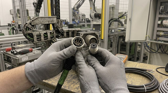
Start with the simplest checks. Look for obvious signs of damage along the cable's length, such as cuts, abrasions, or crushed sections. Pay close attention to the bend radius; a cable bent too tightly can damage the internal foil or braid shield. Ensure the M23 connector backshells at both the motor and drive ends are fully tightened, as they are often a critical part of the shield's ground path.
Mechanical Performance & Service Life Specifications for Dynamic Drag Chains
Repeated flexing inside cable carriers degrades braid shielding strands. Cables must meet strict mechanical parameters based on acceleration and movement profiles.
| Evaluation Parameter | Fixed / Static Wiring | Flexible Motion | High-Speed Continuous Drag Chain | 3D Torsional Robotic Motion |
|---|---|---|---|---|
| Min. Bending Radius (Power Cable) | 5 × Outer Diameter (OD) | 7.5 × OD | 10 × OD | 12 × OD |
| Min. Bending Radius (Encoder Cable) | 6 × OD | 8 × OD | 10 × OD | 12 × OD |
| Flexing Cycles (Braid Integrity) | N/A | ~1,000,000 cycles | ≥ 5,000,000 to 10,000,000 cycles | ≥ 3,000,000 cycles |
| Max. Acceleration / Speed | N/A | 10 m/s² / 180 m/min | 50 m/s² / 300 m/min | Torsional angle ±180°/m |
| Conductor Stranding Class | Class 2 / Class 5 | Class 5 fine bare copper | Class 6 extra-fine tinned copper (Single strand Ø ≤0.08–0.10mm) | Class 6 extra-fine bundled stranding |
Step 2: Test Shield Continuity with a Multimeter
A broken shield offers no protection. You can verify its integrity with a basic multimeter.
- Power Down: Completely power down the machine and disconnect both ends of the M23 cable.
- Set Multimeter: Set your multimeter to the continuity setting (it will beep when probes touch) or the lowest resistance (Ω) setting.
- Test End-to-End Continuity: Touch one probe to the outer metal shell of the M23 connector at one end of the cable. Touch the other probe to the metal shell of the connector at the opposite end.
- Check the Result: You should hear a continuous beep or see a very low resistance reading (typically under 1-2 ohms). If you get no beep or an "OL" (open loop) reading, there is a break somewhere in the shield.
- Check for Shorts: Test for a connection between the shield (connector shell) and each individual pin inside the connector. There should be no continuity. A connection indicates the shield is shorting to a power or signal conductor.
Electrical Ratings, Insulation Resistance, and Thermal Derating
Servo motor power surges can breakdown low-grade insulation. The table below outlines electrical constraints per IEC 61984 standards for M23 power and signal configurations.
| M23 Pin Layout / Application | Wire Gauge (AWG / mm²) | Rated Voltage | Impulse Dielectric Withstand | Max Contact Resistance | Insulation Resistance | Thermal Derating Factor |
|---|---|---|---|---|---|---|
| 6-Pin / 8-Pin (Servo Power: 3+PE+2) | 1.5 mm² – 4.0 mm² (16–11 AWG) | 630 V AC / 850 V DC | 6.0 kV / 1 min | ≤ 1.5 mΩ | ≥ 100 MΩ | 100% @ 40°C; 80% @ 60°C; 55% @ 80°C |
| 12-Pin / 17-Pin (Incremental Encoder) | 0.14 mm² – 0.5 mm² (26–20 AWG) | 160 V AC/DC | 1.5 kV / 1 min | ≤ 3.0 mΩ | ≥ 100 MΩ | Temperature rise ΔT < 20K under rated signal load |
| 9-Pin (Resolver / Absolute Encoder) | 0.25 mm² – 0.75 mm² (24–18 AWG) | 250 V AC/DC | 2.5 kV / 1 min | ≤ 2.5 mΩ | ≥ 100 MΩ | Signal cross-talk isolation > 60 dB |
Upgrade Paths for Noisy Environments
If your inspection and testing confirm the cable is a problem, or if you continue to have issues with a new but basic cable, it's time to consider an upgrade. Not all shields are created equal.
- Foil Shield: A single layer of aluminum foil provides 100% coverage and is effective against high-frequency interference. However, it can be fragile and has higher electrical resistance than a braid.
- Braid Shield: A woven braid of tinned copper wires is mechanically durable and provides a very low-resistance path to ground, making it effective against lower-frequency noise. Its coverage is typically 85-95%.
- Braid-and-Foil Shield (Double Shielding): For demanding applications, this is the most effective solution. It combines a 100% coverage foil layer with an overlying, durable braid. This construction offers the best protection across a wide frequency range and is the standard for heavy-duty, high-performance servo cable assemblies.
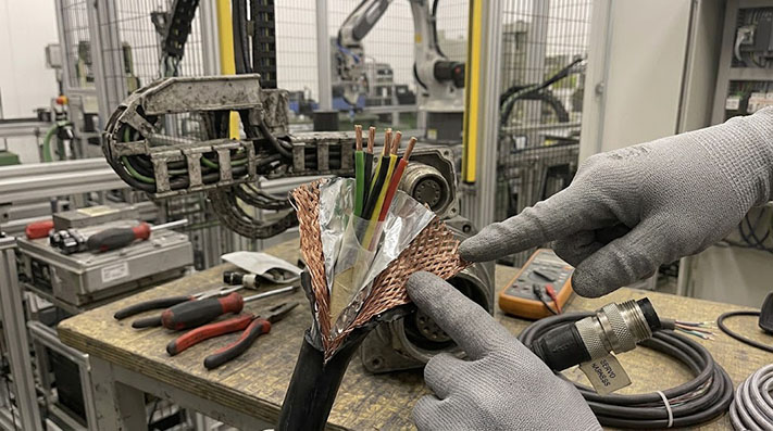
In environments with multiple high-power drives, long cable runs, or cables routed in trays with other noise sources, a standard foil-only shield is often insufficient. Upgrading to a cable with a braid-and-foil shield is a direct and reliable fix for EMI-related problems.
Shielding Construction & High-Frequency EMC Attenuation Performance
In VFD and servo drive applications, high dV/dt PWM switching generates severe conducted and radiated EMI. Shielding effectiveness is quantified by transfer impedance and optical coverage.
| Shielding Construction Type | Optical / Braid Coverage | Transfer Impedance (@ 30 MHz) | Shielding Attenuation (30 MHz – 1 GHz) | Mechanical Durability in Dynamic Flexing | Optimal Application Profile |
|---|---|---|---|---|---|
| Aluminum Mylar Foil Only | 100% | > 300 mΩ/m | ~20 dB to 30 dB | Poor (Foil micro-cracking under flexing) | Static cabinet internal wiring; low-vibration environments |
| Single Tinned Copper Braid | ≥ 85% | < 100 mΩ/m | ~45 dB to 60 dB | Good (High tensile strength) | Standard motor power cables; low-EMI environment |
| Double Shield (Foil + Tinned Copper Braid) | 100% + ≥ 85% | < 10 mΩ/m | ≥ 80 dB (Ultra-high containment) | Very High | Servo power & encoder combination cables near high-noise drives |
| S/FTP (Individual Pair Foil + Overall Braid) | 100% per pair + 85% overall | < 5 mΩ/m | ≥ 95 dB | Extremely High | High-resolution Absolute Encoders (EnDat 2.2, Hiperface DSL, DRIVE-CLiQ) |
Specifying the Right M23 Cable for Your Application
If you are experiencing persistent servo motor noise, position errors, or false alarms, the cable assembly is a critical component to evaluate. A basic cable may not be sufficient for your specific drive, motor, and plant environment.
When requesting a quote for a replacement M23 servo or encoder cable, be prepared to share the details of your setup. Describing your symptoms and providing information—such as the drive and motor models, required cable length, and routing conditions—allows a supplier to recommend a cable assembly with the appropriate shielding and construction for a more stable and reliable system.
Cable Jacket Material Selection Matrix for Severe Industrial Environments
Chemical attack from coolants or mechanical abrasion destroys cable jackets, exposing braid shields to moisture and grounding faults.
| Cable Jacket Compound | PUR (Polyurethane) | Heavy-Duty PVC | TPE (Thermoplastic Elastomer) |
|---|---|---|---|
| Operating Temperature (Dynamic) | -40°C to +90°C | -10°C to +80°C | -50°C to +105°C |
| Industrial Coolant / Cutting Oil Resistance | Superior (UL 1581 / DIN EN 60811-404) | Moderate | Excellent |
| Microbial & Hydrolysis Resistance | High | Low | High |
| Abrasion & Tear Propagation Resistance | Exceptional | Moderate | Very High |
| Flame Retardancy & Halogen Status | UL 94-V0, Low Smoke Zero Halogen (LSZH) | UL 94-V1 | UL 94-V0, LSZH |
| Recommended Application Profile | CNC Machining Centers, Continuous Drag Chains, Oily Environments | Low-stress fixed cabinet-to-motor wiring | Extreme low-temperature outdoor or arctic robotics |
Mechanical Grounding & Assembly Torque Specifications
A high-quality braid shield is useless if the connector termination introduces a high-impedance ground bottleneck. Achieving true 360° EMC shielding requires strict assembly controls.
| Assembly Feature / Parameter | Engineering Specification | Practical Quality Control Point |
|---|---|---|
| EMC Shield Termination Type | 360° Metallic Crown Spring / Iris Spring Clamp | Avoid pig-tailing braid wires; braid must be folded back evenly over the 360° brass spring sleeve. |
| Shield-to-Shell DC Ground Resistance | < 2.0 mΩ (measured end-to-end) | Resistance above 5 mΩ indicates oxidation or incomplete 360° braid contact inside the backshell. |
| M23 Coupling Nut Torque | 2.5 Nm – 3.0 Nm (Use torque wrench) | Insufficient torque loosens internal O-ring under vibration, leading to shield ring oxidation. |
| Cable Gland Strain Relief Torque | 3.0 Nm – 4.5 Nm | Prevents tensile strain on the internal shield termination during dynamic drag chain motion. |
| Ingress Protection (Mated) | IP67 / IP68 (2m / 24h) | Protects silver/gold-plated contacts and braid junction from fluid-induced galvanic corrosion. |