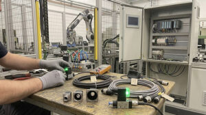

An intermittent network connection is one of the most frustrating problems on a modern factory floor[cite: 11]. One minute, your HMI, vision system, or robot is communicating perfectly; the next, it drops offline, halting production[cite: 11]. When the connection uses M12 industrial Ethernet cables, the cause often lies in a handful of common physical and environmental issues[cite: 11].
A systematic approach is the fastest way to find the root cause and restore a stable connection[cite: 11]. Start with the most likely culprits at the physical layer before moving to network settings[cite: 11]. This checklist guides a maintenance engineer through diagnosing intermittent connection drops, from the connector pins to the network switch port[cite: 11].
Start with Physical Layer Checks
Intermittent failures are frequently caused by physical problems that change with vibration, temperature, or machine movement[cite: 11]. Before suspecting a complex network issue, perform a thorough visual and physical inspection of the M12 cable assembly[cite: 11].
Physical Layer Specifications: M12 D-Code vs. X-Code Ethernet
Understanding the physical layer parameters and signal integrity limits of M12 D-Code and X-Code architectures is vital when diagnosing packet drops and bit error rate (BER) spikes:
| Physical & Electrical Parameter | M12 D-Code (Fast Ethernet) | M12 X-Code (Gigabit / 10G) | Testing Standard & Requirement |
|---|---|---|---|
| Transmission Protocol Standard | 100BASE-TX (PROFINET / EtherCAT) | 1000BASE-T / 10GBASE-T | IEEE 802.3 Ethernet Standards |
| Data Rate & Operating Bandwidth | 100 Mbps at 100 MHz | 1 Gbps / 10 Gbps at 500 MHz | IEC 61076-2-101 (D) / -109 (X) |
| Wiring & Pair Architecture | 2-Pair (4-Pole Star Quad) | 4-Pair (8-Pole Individually Shielded) | Inner X-Shield Cross-Separator |
| Near-End Crosstalk (NEXT at 100MHz) | ≥ 32.3 dB | ≥ 62.3 dB (High Separation) | TIA-568-C.2 Category 6A |
| Return Loss ($RL$ at 100MHz) | ≥ 20.0 dB | ≥ 28.0 dB | ISO/IEC 11801 Class EA |
| Max Channel Length (24 AWG Solid) | 100 meters | 100 meters | Includes 10m Patch Cord Derating |
| Max Flexing Channel Length (26 AWG) | 80 meters (Stranded Conductor) | 65 meters (High Attenuation Factor) | ISO/IEC 11801 Flexible Cable Factor |
Inspect the Connector Mating Interface
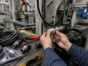
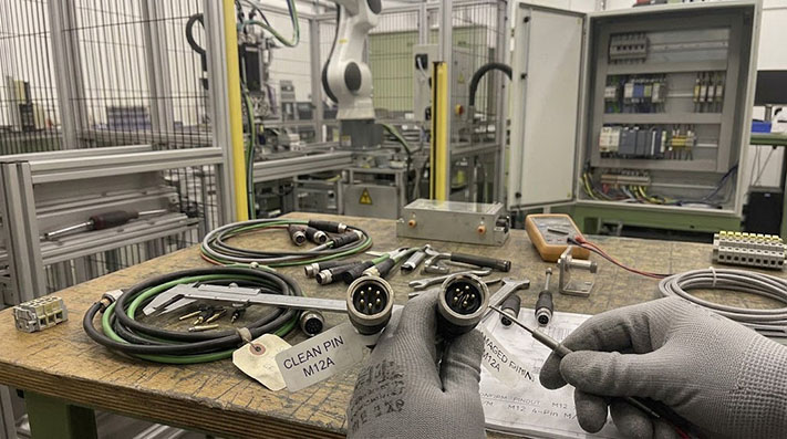
First, ensure the machine is safely powered down and locked out[cite: 11]. Disconnect the M12 connector and examine both the male and female ends under good lighting[cite: 11].
- Bent or Recessed Pins: Look for any pins that are bent, pushed back into the connector housing, or contaminated[cite: 11]. A single damaged pin can cause a total loss of signal or intermittent contact[cite: 11].
- Contamination: Debris, metal shavings, or dried fluid inside the connector can prevent a solid electrical connection[cite: 11]. Clean the interface with appropriate contact cleaner if necessary[cite: 11].
- Coupling Nut: Is the coupling nut fully tightened[cite: 11]? A loose nut can allow the connection to separate slightly during machine vibration, causing intermittent signal loss[cite: 11]. It should be hand-tightened to the manufacturer's specification to ensure the internal O-ring seal is properly compressed and the electrical connection is secure[cite: 11].
 [cite: 11]
Check the Cable Body and Strain Relief
Inspect the entire length of the cable, paying close attention to areas where it moves or contacts machine surfaces[cite: 11].
- Jacket Damage: Look for cuts, abrasions, or crushed spots on the cable jacket[cite: 11]. Damage to the outer jacket can expose the internal conductors or shielding to physical stress and environmental hazards[cite: 11].
- Bend Radius: Check for sharp, tight bends, especially near the connector backshell[cite: 11]. Exceeding a cable's minimum bend radius can break internal conductors or degrade the shield's effectiveness over time, leading to poor signal integrity[cite: 11].
- Strain Relief: Ensure the strain relief at the back of the M12 connector is intact[cite: 11]. A broken or missing strain relief allows stress to be transferred directly to the solder joints or crimp terminals inside the connector, a common cause of failure in high-vibration applications[cite: 11].
Dynamic Flexing Mechanical & Signal Attenuation Degradation Profile
Continuous mechanical flexing in drag chains alters cable geometry, causing impedance mismatch ($Z_0 neq 100,Omega$) and packet drops:
| Motion Test Profile / Mode | Min. Bend Radius | Conductor Construction | Tested Flexing Life Cycles | Max Attenuation Increase (at 100 MHz) | Failure Mode causing Packet Drops |
|---|---|---|---|---|---|
| Static / Fixed Machine Wiring | 5 × Cable OD | Solid Bare Copper (24 AWG) | N/A | < 22.0 dB / 100m | Cable crushing or sharp edge pinching |
| Continuous Drag Chain Motion | 7.5 × Cable OD | Fine Stranded Copper (26 AWG) | ≥ 5,000,000 Cycles | + 15% Max (Aging Allowance) | Pair geometry deformation altering $Z_0$ |
| High-Speed Long Travel Drag Chain | 10 × Cable OD | Extra-Fine Strands (26 AWG) | ≥ 10,000,000 Cycles | + 20% Max | Braid shield strands snapping & puncturing core |
| 3D Robotic Arm Torsional Motion | 12 × Cable OD | Special Center Core Element | ≥ 3,000,000 Cycles (±180°/m) | + 15% Max | Torsional pair unwinding causing NEXT degradation |
Assess Environmental Factors
Factory environments expose cables to conditions that can degrade performance and cause failures that appear intermittent at first[cite: 11].
EMC Shielding Topology, Transfer Impedance & Interference Immunity
High-power VFDs, servo drives, and welding cells generate high-frequency common-mode noise. Effective M12 shielding topologies maintain signal integrity across long cable runs:
| Cable Shielding Topology | Shield Braid Coverage | Transfer Impedance ($Z_t$ at 10 MHz) | Shielding Attenuation (30MHz – 1GHz) | Industrial EMI Environment Suitability |
|---|---|---|---|---|
| SF/UTP (Braid + Foil Outer Shield) | ≥ 85% Braid | ≤ 10 mΩ/m | ~50 dB – 60 dB | Standard conveyor lines, cabinet-to-cabinet routing |
| S/FTP (Individual Foil + Outer Braid) | ≥ 90% High-Density | ≤ 3 mΩ/m (Ultra-Low) | ≥ 80 dB (Maximum Shielding) | Parallel to 480V power cables, VFD proximity |
| 360° Full Metal Hood Connector Shielding | Continuous Metal Ring | ≤ 5 mΩ Contact Resistance | ≥ 70 dB System-level | Prevents EMC ground loops and high-frequency noise drops |
Oil, Coolant, and Liquid Ingress
Exposure to cutting fluids, oils, and washdown solutions is a primary cause of cable failure[cite: 11]. Even if a connector is rated for ingress protection, a loose coupling nut or damaged O-ring can compromise the seal[cite: 11]. Once fluid gets inside the connector, it can cause short circuits[cite: 11]. Certain chemicals can also make the cable jacket brittle, leading to cracks that allow further ingress[cite: 11].
Temperature Cycling and Vibration
Machines that cycle between hot and cold can cause materials to expand and contract[cite: 11]. Over time, this thermal cycling can loosen electrical connections inside the M12 connector[cite: 11]. Combined with constant machine vibration, a marginally secure contact can easily become an intermittent one[cite: 11]. Check if the connection drops coincide with specific machine cycles or temperature changes[cite: 11].
Investigate Network Switch Port Issues
If the physical cable and its environment check out, the problem might be at the network switch[cite: 11]. These issues are often related to configuration mismatches[cite: 11].
Auto-Negotiation and Speed Mismatches
M12 D-Code (100 Mbps) and X-Code (1/10 Gbps) cables connect devices that often use auto-negotiation to set the correct speed and duplex settings[cite: 11]. Sometimes, this process fails, leading to a mismatch between the device and the switch port[cite: 11]. A port configured for 1 Gbps might struggle to communicate with a device trying to force 100 Mbps, resulting in high error rates and dropped packets[cite: 11].
As a test, try manually setting the speed and duplex on the switch port to match the connected device's requirements (e.g., 100 Mbps/Full Duplex for many D-Code devices) and see if stability improves[cite: 11].
Network Switch Port Diagnostic Counter & Error Cause Matrix
Industrial managed switches (e.g., Siemens SCALANCE, Hirschmann) provide diagnostic counters to pinpoint exact cable and connector failure mechanisms:
| Switch Port Diagnostic Counter | Primary Physical Root Cause | Cable / Connector Fault Mechanism | Corrective Engineering Action |
|---|---|---|---|
| CRC / FCS Frame Errors | High EMI interference or poor shielding | Damaged 360° shield ground or unshielded field connector | Replace with S/FTP factory-molded M12 cable |
| Late Collisions / Alignment Errors | Cable length exceeding max propagation delay | Cable run > 100m or severe impedance discontinuity | Shorten cable length or insert industrial switch repeater |
| Runt Packets / Jabber Counters | Intermittent pin contact loss | Loose coupling nut, oxidized or bent M12 pins | Retighten coupling nut to 0.6 Nm; clean pin interface |
| Link Flaps (Up/Down cycling) | Physical conductor intermittent open-circuit | Broken copper strand inside flexed drag-chain cable | Replace drag-chain cable with high-flex PUR unit |
| TDR Cable Open/Short Distance Test | Physical cut, crush, or moisture ingress | Water capillary ingress into plug housing | Check IP67 gasket seal and replace degraded cable |
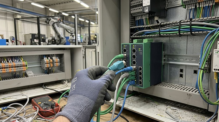
Faulty Port Test
To rule out a faulty switch port, simply move the M12 cable's connection to a different, known-good port on the same switch[cite: 11]. If the problem disappears, the original port may be failing[cite: 11]. If the problem follows the cable to the new port, the issue is almost certainly in the cable or the end device[cite: 11].
 [cite: 11]
The Cable Replacement Decision
After troubleshooting, you may find a definitive fault in the cable assembly[cite: 11]. The decision then becomes whether to attempt a repair or order a replacement[cite: 11].
- Replace the Cable if: The issue is a damaged molded connector, the cable jacket is cut or crushed, there is evidence of liquid ingress, or the cable fails in a high-flex or robotic application[cite: 11]. In these cases, a repair is unreliable[cite: 11]. A new, factory-tested assembly is the most dependable solution[cite: 11].
- A Repair May Be Possible if: The cable uses field-wireable connectors and the problem is a simple termination failure at the end[cite: 11]. This is only advisable if the technician is trained, has the right tools, and the application is not mission-critical[cite: 11]. For most production environments, replacement is the safer and faster option[cite: 11].
Getting the Right Replacement Cable
If troubleshooting points to a cable failure, a well-specified replacement is the fastest path back to stable operation[cite: 11]. When preparing to contact a supplier, have the key details ready[cite: 11]. Note the connector type (M12), coding (D-Code or X-Code), pin count, gender (male/female), and angle (straight or right-angle) for both ends[cite: 11]. Measure the required length and describe the machine and environment it will be used in[cite: 11].
If you are fighting intermittent connection issues and suspect your cables are the cause, ConnecLink can help[cite: 11]. We can review your current cable's specifications and build a replacement assembly designed for the demands of your application[cite: 11]. Send us your requirements, and our team will help you configure a reliable solution[cite: 11].