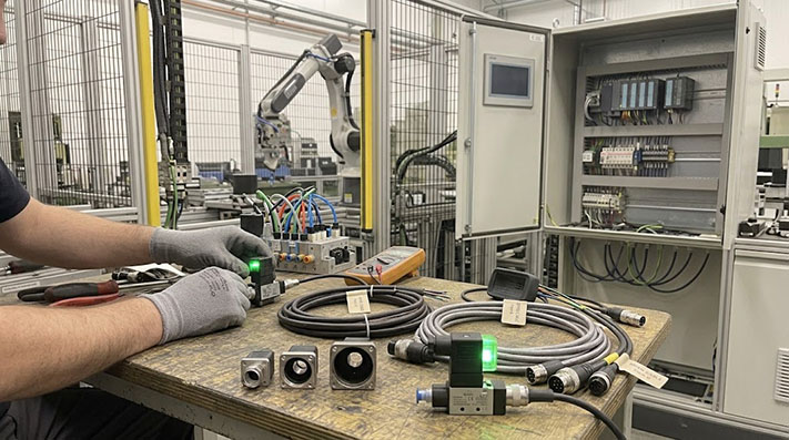
Diagnosing a failed pneumatic or hydraulic solenoid valve on a busy production line often comes down to a single question: Is the failure in the controller, the cable, or the solenoid coil itself?
Solenoid valve connectors equipped with integrated Light Emitting Diodes (LEDs) provide immediate visual feedback on power status. However, relying on these indicator lights requires a clear understanding of how the connector is wired internally, what different LED states signify, and how the physical standards of these connectors differ.
DIN 43650 and EN 175301-803: Understanding the Standards
The square and rectangular connectors used on solenoid valves are governed by industry standards. Originally designated under DIN 43650, these specifications were later harmonized under the international standard EN 175301-803.
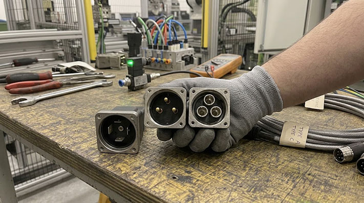
While many technicians still refer to them as "DIN connectors," specifying the correct form factor during maintenance or sourcing is critical. The three primary styles—Form A, Form B, and Form C—are distinguished by pin spacing (pitch), blade width, and the shape of the connector housing.
| Standard Form | Pin Spacing (Pitch) | Blade Configuration | Typical Applications |
|---|---|---|---|
| Form A | 18 mm | 3 flat blades (or 2 blades + 1 ground) | Large pneumatic and hydraulic directional control valves |
| Form B | 10 mm or 11 mm | 2 flat blades + 1 ground | Medium-sized valves, manifold blocks, pressure switches |
| Form C | 8 mm or 9.4 mm | 3 flat or sub-micro pins | Miniature solenoid valves, pilot blocks, space-constrained machinery |
Note: Form B and Form C both have two distinct variants. Form B is available in standard 10 mm pin spacing (often called "Industrial Form") and 11 mm spacing (DIN standard). Form C is available in 8 mm spacing (Industrial) and 9.4 mm spacing (DIN). Interchanging these variants will damage the pins or fail to seal against ingress.
Electrical Ratings, Insulation Limits, and Mechanical Constraints
The table below outlines strict physical and electrical limits compliant with IEC 60664-1 and EN 175301-803 standards.
| Connector Form Factor | Pin Spacing (Pitch) | Max. Wire Gauge (AWG / mm²) | Rated Current (In) | Rated Voltage (Un) | Dielectric Withstand (1 min) | Max. Contact Resistance | Center Screw Thread / Torque |
|---|---|---|---|---|---|---|---|
| Form A (18mm) | 18.0 mm | Up to 1.5 mm² (16 AWG) | 10.0 A | 250V AC / 300V DC | 2,000 V AC | ≤ 4.0 mΩ | M3 × 0.5 ( Torque: 0.4 – 0.5 Nm ) |
| Form B (Industrial 10mm) | 10.0 mm | Up to 1.0 mm² (18 AWG) | 10.0 A | 250V AC / 300V DC | 2,000 V AC | ≤ 5.0 mΩ | M3 × 0.5 ( Torque: 0.4 – 0.5 Nm ) |
| Form B (DIN 11mm) | 11.0 mm | Up to 1.0 mm² (18 AWG) | 10.0 A | 250V AC / 300V DC | 2,000 V AC | ≤ 5.0 mΩ | M3 × 0.5 ( Torque: 0.4 – 0.5 Nm ) |
| Form C (Industrial 8mm) | 8.0 mm | Up to 0.75 mm² (20 AWG) | 6.0 A | 125V AC / 150V DC | 1,500 V AC | ≤ 8.0 mΩ | M2.5 × 0.45 ( Torque: 0.25 – 0.3 Nm ) |
| Form C (DIN 9.4mm) | 9.4 mm | Up to 0.75 mm² (20 AWG) | 6.0 A | 125V AC / 150V DC | 1,500 V AC | ≤ 8.0 mΩ | M3 × 0.5 ( Torque: 0.3 – 0.4 Nm ) |
Form A, B, and C Pinouts with LED Position Marked
Integrated LED connectors feature a small, transparent or translucent housing section that allows the LED light to shine through. The LED circuit is wired internally in parallel with the load (the solenoid coil).
Because solenoid valves can operate on Alternating Current (AC) or Direct Current (DC), the internal circuitry of the connector determines its polarity requirements. AC/DC universal connectors typically utilize a bi-directional LED or a bridge rectifier, whereas DC-only connectors utilize a polarized LED that requires positive voltage on a specific pin to illuminate.
Pin Assignment and Internal Schematic
In standard 2-pole plus ground configurations (the most common setup for LED-equipped valve cables), the wiring assignments follow a strict layout:
- Pin 1: Positive (+) for DC systems, or Line (L1) for AC systems.
- Pin 2: Negative (-) for DC systems, or Neutral (N) for AC systems.
- Pin 3: Typically unused in 2-pole configurations, or used for an auxiliary signal in 3-pole systems (rarely used with LEDs).
- Ground (PE): The flat blade oriented perpendicular to the active pins, marked with the ground symbol. It connects directly to the valve frame for safety.
As shown in the circuit schematic, the LED is connected directly across Pin 1 and Pin 2. In professional-grade overmolded cables, this circuit also contains a Varistor (VDR) or a Transient Voltage Suppressor (TVS) diode. When the PLC switches the solenoid coil off, the magnetic field inside the coil collapses, generating a high-voltage back-EMF spike. The suppression circuit clamps this spike to protect the PLC output card and prevent premature LED burnout.
Transient Voltage Suppression & Back-EMF Protection Specifications
Inductive load switching of solenoid coils generates rapid dI/dt high-voltage spikes (up to 1,000V Back-EMF). Integrated suppression circuits protect PLC transistor outputs and relay contacts.
| Suppression Protection Type | Circuit Topology / Components | Max. Clamping Voltage (Vc) | Response Time (t_rr) | Peak Surge Current (8/20 µs) | Polarity Sensitivity | Primary Application Profile |
|---|---|---|---|---|---|---|
| Varistor (MOV) | Metal-Oxide Varistor across Pin 1 & 2 | ~68V (for 24V system) | < 25 ns | Up to 250 A – 500 A | Bi-directional (AC/DC) | Heavy-duty AC/DC hydraulic valves with high energy storage |
| TVS Diode (Transil) | Bidirectional Suppression Diode | ~38V (Ultra-precise) | < 1 ps (Picosecond) | ~100 A | Bi-directional (AC/DC) | High-speed, fast-switching pneumatic valves near sensitive PLCs |
| Flyback Diode (DC) | Standard Rectifier Diode (1N4007) | ~0.7V to 1.2V | ~2 µs (Slow cutoff) | 10 A – 30 A | Strictly Polarized (DC Only) | Cost-sensitive static DC valves; note: delays mechanical valve drop-out |
| RC Snubber Circuit | Series Resistor + Capacitor | Over-damped sine wave | Immediate | Non-applicable (Energy absorption) | Bi-directional (AC/DC) | High-voltage AC 110V/230V solenoid networks |
What Steady On, Blinking, and Off Mean for Your Coil Status
Using the LED as a diagnostic tool requires knowing what the light actually measures. Because the LED is in parallel with the coil, it indicates the presence of voltage at the connector terminals, not necessarily current flowing through the coil winding.
1. LED is Steady On
- What it means: The control system (PLC or manual switch) is successfully delivering correct operating voltage to the connector terminals.
- Is the valve working? Usually yes. However, if the LED is on but the valve fails to actuate, the failure point is mechanical or internal to the coil. The coil winding may be open-circuited (burnt out), the valve spool may be jammed by debris, or pilot air pressure may be insufficient.
- How to verify: Measure the resistance across Pin 1 and Pin 2 with the connector unplugged. An open circuit (infinite resistance) indicates a dead coil that must be replaced.
2. LED is Off
- What it means: There is no voltage reaching the LED circuit inside the connector.
- Is the valve working? No. The solenoid cannot actuate without power.
- Possible causes:
- The PLC output is turned off.
- A blown fuse in the control cabinet.
- A broken conductor inside the valve cable.
- On DC-only connectors, reversing the polarity (+ on Pin 2 and - on Pin 1) will keep the LED dark, though the solenoid coil itself may still click and operate.
- How to verify: Use a multimeter to check for voltage at the female terminals of the cable connector while the control system commands the valve to open.
3. LED is Blinking, Flickering, or Dim
- What it means: Unstable voltage supply or high-resistance contact points.
- Possible causes:
- Contact corrosion: Moisture entry has oxidized the pins, creating a high-resistance bridge.
- Loose mounting screw: The center retention screw of the connector has backed out, causing the female terminals to vibrate off the male pins.
- PWM signal: If the valve is a proportional control valve rather than a simple on/off valve, the controller may be pulsing the power. A fast pulse-width modulation (PWM) signal will cause the LED to dim or flicker rapidly.
- Contact bounce: An upstream relay contact is failing or bouncing under load.
Extending vs. Replacing: Repair Options for Damaged Valve Cables
When a solenoid valve cable is severed, pinched by machine movement, or degraded by exposure to cutting fluids and oils, maintenance teams must choose between repairing the existing line or replacing the assembly.
Option A: Extending or Splicing the Cable
Splicing a broken valve cable on the factory floor using wire nuts, electrical tape, or standard heat-shrink butt connectors is a common emergency measure.
- The Risk: Solenoid valves are frequently mounted directly on pneumatic manifolds or hydraulic power units where they are exposed to vibrations, washdown water, or oil mist. A manual splice degrades the overall Ingress Protection (IP) rating of the cable. Moisture entering a splice will travel inside the cable jacket via capillary action, eventually reaching the connector pins and causing short circuits or corrosion.
- When to do it: Only as a temporary fix to keep production running until the scheduled maintenance shift.
Option B: Replacing with a Field-Attachable Connector
Field-attachable DIN connectors allow maintenance teams to wire bulk cable directly into a rebuildable housing using screw terminals.
- The Advantage: Allows custom cable lengths to be determined on-site.
- The Drawback: Achieving a reliable IP65 or IP67 seal depends entirely on the technician's skill in tightening the cable gland PG thread and properly seating the rubber gasket. Over-tightening can strip the plastic threads, while under-tightening permits moisture entry.
Option C: Replacing with a Molded Cable Assembly
Molded cable assemblies feature a polyurethane (PUR) or polyvinyl chloride (PVC) connector body that is permanently overmolded onto the cable.
- The Advantage: The overmolding process seals the cable entry point completely against liquids, dust, and industrial oils, providing reliable IP67 protection. The integrated LED and suppression circuit are completely encased in protective resin, making them impervious to machine vibration.
- The Drawback: Requires stocking pre-determined cable lengths (e.g., 2-meter, 5-meter, or 10-meter runs).
Dynamic Mechanical Specifications for Motion Control & Drag Chain Applications
Solenoid valves installed on gantry systems or robotic end-effectors require continuous-flex rated cables to prevent inner conductor fatigue.
| Parameter / Cable Rating | Static / Fixed Installation | Flexible Machine Motion | High-Speed Drag Chain Motion | Robotic Torsional Motion |
|---|---|---|---|---|
| Min. Bending Radius (PUR Jacket) | 5 × Cable OD | 7.5 × Cable OD | 10 × Cable OD | 12 × Cable OD |
| Min. Bending Radius (PVC Jacket) | 6 × Cable OD | 10 × Cable OD | Not Recommended | Not Recommended |
| Bending Cycles (PUR Outer Jacket) | N/A | ~1,000,000 cycles | ≥ 5,000,000 to 10,000,000 cycles | ≥ 3,000,000 cycles |
| Max. Acceleration / Traverse Speed | N/A | 5 m/s² / 120 m/min | 20 m/s² / 240 m/min | Torsional angle ±180°/m |
| Conductor Stranding Class | Class 2 / Class 5 Bare Copper | Class 5 Fine Bare Copper | Class 6 Extra-Fine Tinned Copper (Ø ≤0.08mm) | Class 6 Bundled Extra-Fine Strands |
Technical Specifications to Confirm Before Ordering
To avoid sourcing mismatches that lead to machine downtime, verify the following details before requesting a replacement solenoid valve cable:
- Form Factor: Confirm Form A (18 mm), Form B (10 or 11 mm), or Form C (8 or 9.4 mm).
- Operating Voltage: Specify 12V DC, 24V DC, 110V AC, or 230V AC. Installing a 24V LED connector on a 230V circuit will destroy the LED instantly; installing a 230V LED connector on a 24V circuit will result in an LED that never lights up.
- Circuit Protection: Determine if your control system requires an integrated varistor (VDR) or diode to clamp voltage spikes.
- Jacket Material: Choose PVC for standard static applications, or PUR for environments involving continuous bending (drag chains), exposure to cutting oils, or low ambient temperatures.
- Cable Length and Termination: Define the overall length and whether the free end should be pigtailed (stripped and tinned) or equipped with an M12 connector for quick-disconnect integration.
Environmental & Chemical Compatibility Matrix (Jacket & Gasket Materials)
Chemical attack from hydraulic fluids or coolant mists degrades gaskets and jacket polymers, causing capillary water ingress and dead shorts.
| Chemical / Environmental Factor | PUR Jacket + NBR Gasket | PVC Jacket + NBR Gasket | TPE Jacket + FKM (Viton) Gasket |
|---|---|---|---|
| Operating Temperature Range | -40°C to +90°C | -10°C to +70°C | -50°C to +125°C |
| Hydraulic Oils & Mineral Lubricants | Superior | Moderate | Exceptional |
| CNC Cutting Coolants / Emulsions | Superior (DIN EN 60811-404) | Poor (Softens & Swells) | Superior |
| Washdown / Hydrolysis Resistance | Excellent (Ether-based PUR) | Moderate | Exceptional |
| Ozone & UV Weathering Resistance | High | Moderate | Superior |
| Ingress Protection (Mated Torque) | IP67 / IP68 | IP65 | IP67 / IP68 / IP69K (Washdown) |
Installation Torque & Field-Assembly Quality Control Standards
Achieving a long-term IP67/IP68 seal and preventing contact oxidation requires strict torque verification during field assembly or replacement.
| Assembly Feature / Parameter | Engineering Standard | Practical Torque & QC Specification |
|---|---|---|
| Form A / B Center Retaining Screw | ISO 4762 / DIN 912 Stainless Steel | 0.4 Nm – 0.5 Nm (Use torque screwdriver; over-tightening crushes seal housing) |
| Form C Center Retaining Screw | ISO 4762 Stainless Steel | 0.25 Nm – 0.35 Nm |
| Cable Gland Strain Relief Nut (PG9/PG11) | EN 62444 | 2.5 Nm – 3.5 Nm (Ensures full IP67 compression on cable jacket) |
| Field-Attachable Screw Terminals | IEC 60999-1 | 0.22 Nm – 0.25 Nm (Prevents stranded wire shearing) |
| Flat Profile Gasket Sealing Compression | Nitrile (NBR) / Silicone | 20% – 30% nominal compression across the entire perimeter |
Need a Drop-in Replacement for Your Valve Cable?
ConnecLink provides factory-molded Form A, Form B, and Form C solenoid valve connector cables equipped with high-visibility LEDs and integrated surge suppression.
If you need to replace an existing assembly, simply send us the manufacturer part number or a clear photo of your connector face and cable label. Our team will provide a direct, fully compatible cross-reference.