
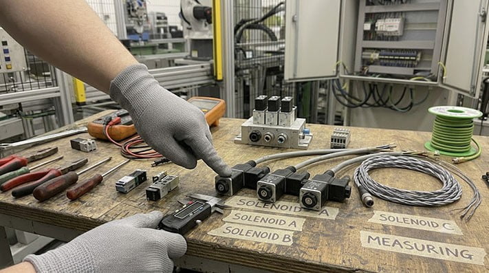
When you need to connect or replace a cable on a pneumatic or hydraulic solenoid valve, the first question is always the same: is it Form A, Form B, or Form C? Choosing the wrong connector can lead to ordering delays, installation problems, and equipment downtime.
These "form factors," originally defined by DIN 43650 and now by EN 175301-803, standardize the physical interface between the valve coil and the electrical connector. While they look similar, they are not interchangeable. This article provides a clear comparison of Form A, B, and C connectors to help you identify the correct type for your application.

Form A, B, and C: Key Differences at a Glance
The quickest way to distinguish between the three forms is to measure the pin spacing and observe the connector's shape. Use this table as a quick reference.
| Feature | Form A | Form B | Form C |
|---|---|---|---|
| Pin Spacing | 18 mm | 10 mm or 11 mm | 8 mm or 9.4 mm |
| Connector Shape | Large, square base | Rectangular base | Small, square base |
| Gasket Profile | Square | Rectangular | Square |
| Common Pinout | 2-pin + Ground, 3-pin + Ground | 2-pin + Ground | 2-pin + Ground, 3-pin + Ground |
| Ground Pin | U-shaped (12 o'clock position) | Offset spade (two possible orientations) | Central spade (6 o'clock position) |
1. Physical Size and Pin Spacing
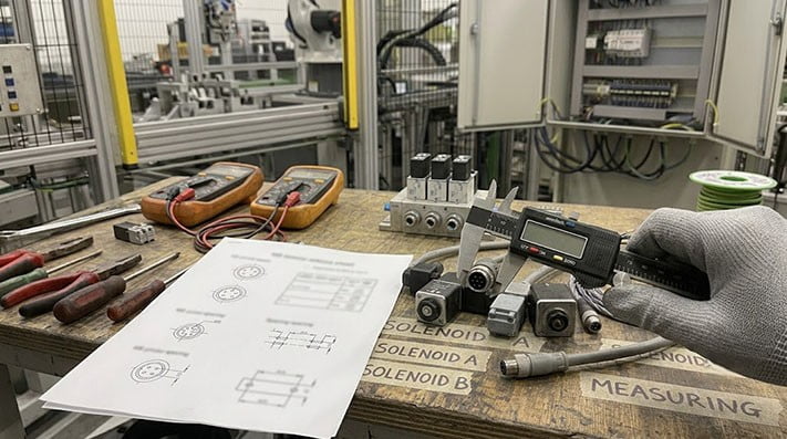
The most reliable identifier is the distance between the two main power pins.
-
Form A: With an 18mm pin spacing, Form A is the largest of the three. It is typically used on larger, higher-power hydraulic and pneumatic valves where more robust connections are needed. Its square base and gasket are easy to recognize.
-
Form B: Form B connectors have a rectangular shape and a pin spacing of either 10mm or 11mm. They are common on smaller valves, such as those found in mobile equipment and compact pneumatic valve manifolds where space is a constraint.
-
Form C: As the smallest of the group, Form C features an 8mm or 9.4mm pin spacing and a compact square housing. This makes it ideal for miniature valves used in instrumentation, pilot valves, and dense automation systems.
2. Grounding Pin Location and Orientation
Beyond size, the ground pin's location and shape are critical differences that prevent incorrect mating.
- Form A: The ground pin is located at the top ("12 o'clock") position, opposite the central screw. It has a distinctive U-shape.
- Form B: The ground pin is an offset spade terminal. This means the connector can often be mounted in two orientations, 180 degrees apart, depending on the valve body and cable exit requirements.
- Form C: The ground pin is a central spade terminal located at the bottom ("6 o'clock") position, directly opposite the two power pins.
Mismatched ground pins are a common source of installation failure. Always check that the ground pin on your cable connector matches the receptacle on the valve coil.
3. Specifying Connectors with LED Indicators
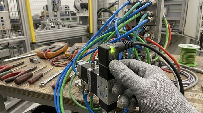
Many solenoid valve connectors are available with built-in LED indicators. These are extremely useful for maintenance and troubleshooting, providing a visual confirmation that the valve is receiving power without needing a multimeter or opening an electrical cabinet.
When ordering a connector with an LED, be sure to specify:
- Operating Voltage: Common options include 12V DC, 24V AC/DC, 110V AC, and 230V AC. Matching the voltage is critical to prevent damage to the LED circuit or the valve coil.
- LED Color: Red or green are standard, allowing for at-a-glance status checks.
- Wiring: Confirm if you need surge suppression or other circuit protection built into the connector head.
Information to Provide for an Accurate Quote
Use this checklist when preparing your inquiry:
- Form Factor: Form A, Form B, or Form C.
- Valve Details (if form is unknown): Provide the valve brand, model number, or a clear photo of the valve's electrical connection pins.
- Pin Configuration: Typically 2-pin + Ground or 3-pin + Ground.
- LED Requirement: Yes or no. If yes, specify the voltage (e.g., 24V DC) and preferred color.
- Cable Length: Specify the required length in meters or feet.
- Termination: Do you need bare wire ends, or a specific connector on the other end?
- Quantity: The number of cable assemblies you require.
- Application Environment: Mention any special conditions, such as exposure to oils, washdown chemicals, or high vibration.
Frequently Asked Questions (FAQ)
1. Can I use a Form B connector on a Form A valve coil? No. The pin spacing, housing size, and gasket shape are different and physically incompatible. You must use a connector that matches the form factor of the valve coil.
2. What is the difference between DIN 43650 and EN 175301-803? EN 175301-803 is the current European standard that has superseded the older German DIN 43650 standard. For practical purposes of identifying Form A, B, and C connectors, the specifications are functionally equivalent.
3. Are solenoid valve connectors waterproof? When properly installed with the gasket and retaining screw tightened, these connectors typically offer good protection against dust and moisture, often meeting ratings like IP65 or IP67[^2]. However, the final IP rating depends on the specific connector design and installation quality. If you have a specific ingress protection requirement for washdown or outdoor use, be sure to specify it in your RFQ.
Get the Right Connector for Your Valve
Don't let connector selection slow down your project. If you're unsure which form factor your valve uses, we can help. Send us the valve brand and model number, or simply attach a clear photo of the coil's connector pins to your inquiry.
Contact us today to request a quote for your Form A, Form B, or Form C solenoid valve cable assemblies.
[^1]: Internal link: "Custom Cable Assemblies - Tianlun Interconnect", https://conneclink.com/custom-cable-assemblies/. Supports: CONNECLINK Custom Cable Assemblies product page provides cable assembly specification and ordering information relevant to the article's emphasis on providing clear connector requirements when requesting a quote. [^2]: "IP ratings - IEC (International Electrotechnical Commission)", https://www.iec.ch/ip-ratings. Evidence role: standard_reference; source type: standards_body; origin: search_result. Supports: IEC 60529 defines the IP (Ingress Protection) Code, including IP65 (dust-tight and protected against water jets) and IP67 (dust-tight and protected against immersion up to 1 meter) ratings. Confirmed via Wikipedia article 'IP code' referencing IEC 60529. Accessed 2026-08-07. Scope note: IEC informational page on IP ratings; full standard document available at webstore.iec.ch/publication/2447.