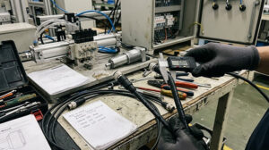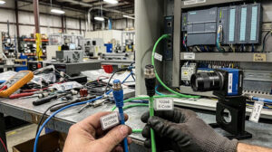
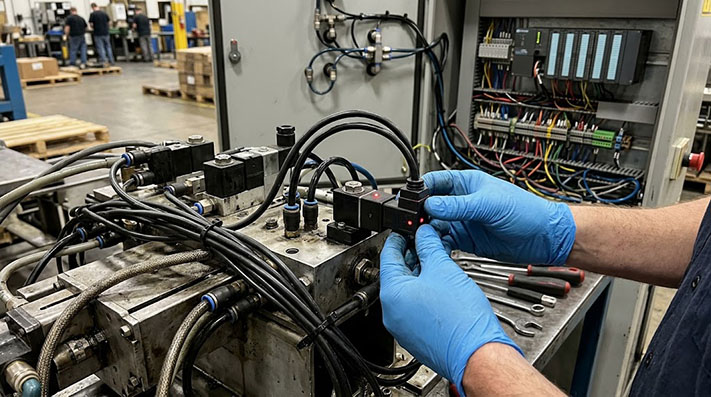
When selecting a connector for a solenoid valve, equipment designers often match the connector form factor to the valve's size and power requirements. Form A connectors are common on large, high-flow valves, while smaller Form B and Form C connectors typically serve compact pneumatic and hydraulic components. However, some applications present a mismatch: the equipment specifies a physically smaller Form C connector for a large valve or a high-power coil.
This situation requires careful specification. While Form C connectors are indeed the smallest of the EN 175301-803 family, they are sometimes the designated interface for demanding applications. Success depends on verifying the complete assembly's electrical capacity, not just its physical shape. The connector housing and the attached cable must be specified to handle the coil's specific voltage and current demands.
Understanding the Form C Interface
Form C solenoid valve connectors, also known as micro connectors, are defined by their compact pin spacing—typically 8 mm or 9.4 mm. This is visibly smaller than the 18 mm spacing of Form A or the 10/11 mm spacing of Form B. They are most often available in 2-pole + ground or 3-pole + ground configurations.
Their small footprint makes them a default choice for miniature pneumatic valves, sensors, and actuators where installation space is extremely limited. Given this common use, finding a Form C interface on a larger process valve or a component with a powerful coil can seem unusual, but it occurs for several reasons:
- Valve Manufacturer Standardization: Some valve brands engineer their products with compact heads or non-standard coil designs that use the Form C interface, even on valve bodies with high flow rates.
- High-Density Manifolds: In complex automation systems, valve manifolds pack numerous valves into a small area. Using a smaller connector like Form C saves valuable space across the entire assembly.
- Legacy Equipment Design: An existing machine design may have been built around a specific valve model that uses a Form C connector, making it the required standard for MRO and replacement parts.
In these cases, the valve's datasheet is the primary source of truth. If it calls for a Form C connector, the task becomes sourcing a connector and cable assembly robust enough for the electrical load.
Physical and Electrical Operating Limits: Form C Standards (DIN 9.4mm vs. Industrial 8mm)
Compliant with EN 175301-803 (formerly DIN 43650) Form C specifications. Designers must verify terminal temperature rise ($Delta T le 30text{K}$) under maximum continuous current loads:
| Physical & Electrical Specification | Form C Industrial Standard (8.0 mm Pitch) | Form C DIN Standard (9.4 mm Pitch) | Engineering Impact on High-Power Coils |
|---|---|---|---|
| Pin Spacing (Center-to-Center Pitch) | 8.0 mm | 9.4 mm | Mismatched pitch destroys terminal spring tension |
| Maximum Conductor Cross-Section | Up to 0.5 mm² (20 AWG) | Up to 0.75 mm² (18 AWG) | 18 AWG reduces conductor heating on sustained high currents |
| Rated Continuous Current ($I_n$) | 6.0 A per Contact | 6.0 A (Standard) / 10.0 A (Heavy-Duty Pin) | Inrush peak must not exceed 3x $I_n$ for >100ms |
| Rated Operating Voltage ($U_n$) | 125V AC / 150V DC | 250V AC / 300V DC | Prevents dielectric arcing between tightly spaced pins |
| Contact Resistance ($R_c$) | ≤ 8.0 mΩ (Precision Brass) | ≤ 5.0 mΩ (Silver/Gold Plated) | Minimizes localized $I²R$ Joule heating inside small shell |
| Center Retaining Screw Thread & Torque | M2.5 × 0.45 (0.25 Nm – 0.30 Nm) | M3 × 0.5 (0.35 Nm – 0.40 Nm) | Over-torquing cracks the micro-polycarbonate body |
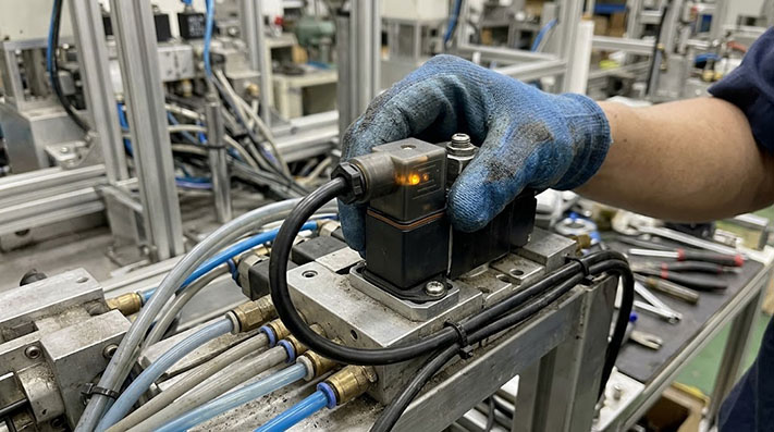
Critical Specifications for High-Current Form C Applications
When a Form C connector is used with a high-power coil, simply matching the "Form C" shape is not enough. The electrical demands of the coil, especially the initial inrush current, can exceed the limits of a standard, off-the-shelf assembly. To ensure a reliable and safe connection, your RFQ or order must address these details.
1. Coil Voltage and Current
This is the most important factor. A connector assembly rated for a 1A holding current may fail when connected to a coil that draws a much higher inrush current upon activation.
- Specify the coil's operating voltage (e.g., 24V DC, 120V AC).
- Provide the holding (continuous) current.
- Provide the inrush (peak) current, if known. High inrush current is a common failure point for underspecified connectors and cables.
2. Cable Conductor Size (AWG)
The wire gauge inside the cable determines its current-carrying capacity. A higher current requires a thicker wire (a lower AWG number) to prevent overheating and excessive voltage drop, which can impair valve performance. A standard cable for a miniature valve might use 22 or 24 AWG wire, which may be insufficient for a coil drawing several amps. Requesting a cable with 18 or 20 AWG conductors may be necessary.
High-Power Coil Current Profiling & Cable Conductor Gauge (AWG) Selection
Solenoid coils exhibit high inductive inrush current ($I{text{inrush}}$) upon energization before settling to steady-state holding current ($I{text{holding}}$). Wire gauge must prevent voltage drop from falling below the minimum valve pull-in threshold (typically 85% $V_n$):
| Nominal Valve Power / Voltage | Inrush Current ($I_{text{inrush}}$ <100ms) | Steady Holding Current ($I_{text{holding}}$) | Minimum Required Wire Gauge | Voltage Drop per 10m Run (24V DC at $I_{text{inrush}}$) | Voltage Drop per 25m Run (24V DC at $I_{text{holding}}$) | Recommended Application Profile |
|---|---|---|---|---|---|---|
| 10W / 24V DC Standard Valve | ~1.8 A | 0.42 A | 22 AWG (0.34 mm²) | 0.19 V (0.8%) | 0.11 V (0.5%) | Compact pneumatic manifold valves |
| 25W / 24V DC High-Power Coil | ~4.5 A | 1.04 A | 20 AWG (0.50 mm²) | 0.31 V (1.3%) | 0.18 V (0.8%) | High-flow hydraulic proportional valves |
| 40W / 24V DC Extreme-Demand Coil | ~8.5 A | 1.67 A | 18 AWG (0.75 mm²) | 0.38 V (1.6%) | 0.19 V (0.8%) | Heavy-duty process automation valves |
| 30VA / 110V AC Solenoid Valve | ~1.5 A | 0.27 A | 20 AWG (0.50 mm²) | 0.32 V (0.3%) | 0.14 V (0.1%) | Industrial fluid/steam process control |
3. Pin Configuration and Wiring
Confirm whether your application requires a 2-pole + ground (2+GND) or 3-pole + ground (3+GND) configuration. This ensures the connector pins align with the valve coil and that your control signals are wired correctly. If the connector includes an LED indicator for visual status, ensure its operating voltage matches your system's supply voltage.
Back-EMF Suppression Circuits and Transient Voltage Protection
Switching off inductive coil loads generates rapid high-voltage spikes (up to 1,000V). Integrated suppression circuits inside the Form C connector housing protect upstream PLC digital outputs and relay contacts:
| Protection Topology / Circuit Component | Max. Clamping Voltage ($V_c$) | Response Time ($t_{rr}$) | Peak Surge Current Absorption (8/20 µs) | Polarity Sensitivity | Primary Application Profile |
|---|---|---|---|---|---|
| Varistor (MOV) | ~68V (for 24V System) | < 25 ns | Up to 250 A | Bi-directional (AC/DC) | Heavy-duty AC/DC hydraulic valves with high energy storage |
| TVS Diode (Transil) | ~38V (Ultra-precise) | < 1 ps (Picosecond) | ~100 A | Bi-directional (AC/DC) | High-speed pneumatic valves installed near sensitive PLCs |
| Flyback Diode (DC) | ~0.7V – 1.2V | ~2 µs (Slow cutoff) | 10 A – 30 A | Strictly Polarized (DC Only) | Cost-sensitive static DC valves; Note: Delays mechanical valve drop-out |
| LED + MOV Combination | ~68V | < 25 ns | ~250 A | Bi-directional (AC/DC) | Visual status diagnostic connectors for high-power coils |
4. Mounting Style and Environment
Form C connectors are available as field-wireable units, where you terminate your own wires, or as factory-molded cable assemblies. Molded assemblies generally offer better protection against moisture and vibration. Also, consider the mounting:
- Direct-to-Coil: The connector mounts directly onto the exposed pins of the valve's coil.
- Base-Mounted: The connector plugs into a receptacle on a valve base or junction block.
The gasket between the connector and the coil is critical for sealing. Ensure the gasket material is compatible with any oils, chemicals, or cleaning solutions in the environment.
Environmental, Chemical & Thermal Compatibility Matrix (Jacket & Gasket Materials)
High-power solenoid coils produce significant internal heat ($>80^circtext{C}$ Continuous). Connector gaskets and cable jacketing must withstand combined thermal stress and chemical exposure:
| Component / Material Grade | Operating Temperature | CNC Coolant & Cutting Oil Resistance | Hydraulic Oil & Mineral Lubricant Resistance | IP Ingress Protection (Correctly Torqued) | Typical Failure Mode under High Heat |
|---|---|---|---|---|---|
| PVC Cable Jacket + NBR Gasket | -10°C to +70°C | Poor (Softens & Swells) | Moderate | IP65 | Thermal hardening, cracking, water capillary ingress |
| PUR Cable Jacket + NBR Gasket | -40°C to +90°C | Superior (DIN EN 60811-404) | Superior | IP67 | Excellent balance for dynamic drag-chain applications |
| TPE Cable Jacket + FKM (Viton) Gasket | -40°C to +125°C | Exceptional | Exceptional | IP67 / IP68 | Premium choice for high-temperature continuous duty coils |
| Silicone (VMQ) Profile Flat Gasket | -50°C to +180°C | Moderate | Poor | IP67 | Extreme ambient/coil temperature applications |
Dynamic Mechanical Endurance in Cable Track Applications
When Form C valve connectors are deployed on moving gantries, robotic end-effectors, or automated tool changers, continuous flexing can cause conductor wire fatigue. Select cable assemblies conforming to these mechanical thresholds:
| Mechanical Motion Parameter | Fixed / Static Wiring | Standard Continuous Drag Chain | High-Speed Drag Chain Motion | Torsional Motion (Robotic Arms) |
|---|---|---|---|---|
| Min. Bending Radius (PUR Outer) | 5 × Cable OD | 7.5 × Cable OD | 10 × Cable OD | 12 × Cable OD |
| Conductor Stranding Class (IEC 60228) | Class 5 Fine Copper | Class 6 Extra-Fine Copper | Class 6 Extra-Fine Tinned Copper (Ø ≤0.08mm) | Class 6 Extra-Fine Bundled Strands |
| Tested Flexing Life Cycles | N/A | ~2,000,000 Cycles | ≥ 5,000,000 to 10,000,000 Cycles | ≥ 3,000,000 Cycles |
| Max. Acceleration / Traverse Speed | N/A | 10 m/s² / 180 m/min | 50 m/s² / 300 m/min | Torsional angle ±180°/m |
A Note on Terminology: Form C vs. Mini-DIN
The term "Form C" specifically refers to connectors compliant with the EN 175301-803 standard (formerly DIN 43650). It should not be confused with "Mini-DIN" connectors. Mini-DIN is a separate family of circular connectors used for data, audio, and video signals (like S-Video or PS/2 keyboard ports) and is not interchangeable or suitable for industrial solenoid valve applications.
Specifying the Right Form C Cable Assembly
Using a Form C connector for a large valve or high-power coil is an application-specific decision driven by the equipment's design. While less common than using a larger Form A connector, it can be a perfectly reliable solution when the connector and cable assembly are properly specified to handle the electrical load.
If you are working with large valves or high-demand coils that require a Form C interface, providing detailed electrical requirements is key. When preparing your RFQ, share the coil voltage, current demands (inrush and holding), and any valve part numbers you have. Our team can help confirm the compatibility of a Form C connector and specify a robust cable assembly to match your application's needs.