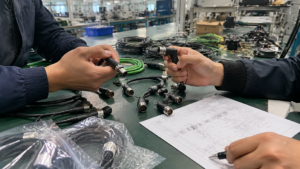
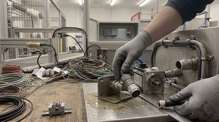
To connect a servo motor to its drive, you need a cable assembly that is more than just a wire. It’s a critical machine component that handles power, transmits precise encoder feedback, and must survive the operating environment. Ordering a custom M23 servo cable assembly without a complete specification can lead to delays, incorrect quotes, and cables that fail in the field.
A complete specification is the foundation for an accurate quote and a reliable cable. To properly define your M23 servo motor and encoder cable needs, you must gather detailed information about your equipment, the physical layout of the machine, and the application environment.
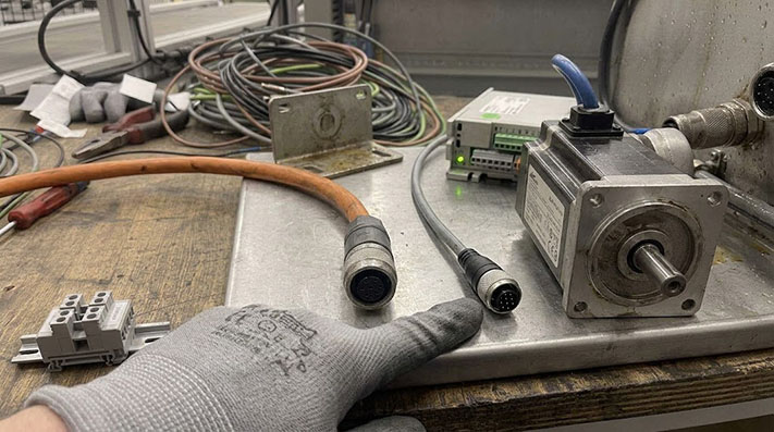
Required Information: The Core Specification Checklist
Before sending a request for quotation (RFQ), work through this checklist. Having these details prepared ensures your supplier can quote the correct M23 power and encoder cables for your system.
1. Equipment Identification
This is the most critical information. A supplier cannot guess the correct pinout or electrical requirements.
- Servo Drive Manufacturer and Model Number: (e.g., Rockwell Kinetix 5700, Siemens SINAMICS S210)
- Servo Motor Manufacturer and Model Number: (e.g., Kollmorgen AKM23F, Fanuc alpha i-F series)
- Drawings or Pinout Diagrams: If you have the connector pin assignments for both the drive and motor ends, provide them. This is the best way to prevent errors.
2. Physical and Mechanical Requirements
Describe the cable's physical form and how it will be installed.
- Total Cable Length: Specify the length in meters or feet from connector to connector. Always confirm your measurement; ordering a cable that is too short is a costly mistake.
- Power and Encoder Cables: Are they separate lengths or should they be equal?
- Routing Path: Will the cable be routed in a fixed position or will it move?
- Dynamic Application Details: If the cable moves, specify the type of motion:
- Continuous flex in a cable track (drag chain)? If so, what is the bend radius of the track?
- Torsional or twisting motion (e.g., on a robotic arm)?
- Connector Orientation: Specify straight or right-angle connectors for both the motor and drive ends. A right-angle connector can solve clearance issues in tight spaces.
Dynamic Mechanical Endurance for Drag Chain and Robotic Arm Motion
Servo cables installed in dynamic cable carriers or multi-axis articulated robots require specialized stranding profiles and polyurethane (PUR) jacketing to withstand mechanical stress:
| Motion Profile / Test Mode | Min. Bending Radius Factor | Conductor Stranding Spec (IEC 60228) | Tested Flexing / Torsional Life Cycles | Max. Acceleration ($a_{text{max}}$) | Max. Traverse Speed ($v_{text{max}}$) |
|---|---|---|---|---|---|
| Fixed / Static Machine Routing | 5 × Cable OD | Class 5 Fine Bare Copper | N/A | N/A | N/A |
| Standard Continuous Drag Chain | 7.5 × Cable OD | Class 6 Extra-Fine Bare Copper | ≥ 5,000,000 Cycles | 10 m/s² | 180 m/min |
| High-Speed Long-Travel Drag Chain | 10 × Cable OD | Class 6 Bundled Tinned Strands | ≥ 10,000,000 Cycles | 50 m/s² | 300 m/min |
| Robotic Torsional Motion (3D) | 12 × Cable OD | Extra-Fine Strands with Center Core Element | ≥ 3,000,000 Cycles (at ±180°/m) | 20 m/s² | 180°/sec Angular Velocity |
3. Application Environment
The environment determines the required durability of the cable jacket and connectors.
- Exposure to Liquids: Will the cable be exposed to cutting fluids, oils, coolants, or washdown procedures? If so, specify the chemical types.
- Temperature: What is the ambient operating temperature range?
- Abrasives: Is the cable likely to be rubbed against machine surfaces or exposed to metal chips?
- UV Exposure: Will the cable be used outdoors or near a UV light source?
Power Cable Considerations: Motor, Amperage, and Length
The M23 power cable delivers the current needed for the motor to generate torque. Selecting the right conductor size (gauge) is a matter of safety and performance.
- Motor Amperage: Provide the motor's peak and continuous current (amp) ratings from its datasheet.
- Voltage Drop: Longer cable runs can cause a drop in voltage, potentially affecting motor performance. The combination of motor amperage and cable length is used to calculate the minimum required conductor gauge to prevent excessive voltage drop and overheating.
An undersized power cable can overheat, creating a fire hazard and causing unpredictable motor behavior. Always provide the motor's electrical data to your cable supplier.
Power Conductor Sizing, Continuous Ampacity, and Voltage Drop Matrix
Conductor gauge selection must account for both continuous current ($I_{text{cont}}$) thermal dissipation and long-distance voltage drop ($Delta V$) during motor peak torque acceleration:
| Power Wire Gauge (AWG / mm²) | Rated Current ($I_{text{cont}}$ at 40°C) | Continuous Conductor Resistance ($R_DC$ at 20°C) | 50m Loop Voltage Drop at 10A ($Delta V$) | 50m Loop Voltage Drop at 30A ($Delta V$) | Recommended Servo Motor Power Rating (400V AC) |
|---|---|---|---|---|---|
| 18 AWG (0.75 mm²) | 12.0 A | ≤ 26.0 Ω/km | 26.0 V (6.5%) | Unsafe (Exceeds Thermal Limit) | Up to 1.5 kW |
| 16 AWG (1.5 mm²) | 18.0 A | ≤ 13.3 Ω/km | 13.3 V (3.3%) | 39.9 V (10.0% - Critical) | 2.0 kW – 3.0 kW |
| 14 AWG (2.5 mm²) | 26.0 A | ≤ 7.98 Ω/km | 7.98 V (2.0%) | 23.9 V (6.0%) | 4.0 kW – 5.5 kW |
| 12 AWG (4.0 mm²) | 34.0 A | ≤ 4.95 Ω/km | 4.95 V (1.2%) | 14.8 V (3.7%) | 7.5 kW – 11.0 kW |
| 10 AWG (6.0 mm²) | 45.0 A | ≤ 3.30 Ω/km | 3.30 V (0.8%) | 9.90 V (2.5%) | 13.0 kW – 15.0 kW |
Encoder Cable Details: Signal Type and Connector Configuration
The encoder cable is a sensitive data line that transmits the motor's exact position, speed, and direction back to the drive. Signal integrity is everything.
- Encoder Type: Specify if the motor uses an incremental, absolute, or resolver-based feedback system. Different encoder types have different wiring and shielding requirements.
- Signal Requirements: If you know the protocol (e.g., Hiperface, EnDat, DRIVE-CLiQ), provide it. This information is typically found in the motor or drive documentation.
- Shielding: Proper shielding is essential to protect the low-voltage encoder signals from electromagnetic interference (EMI) generated by the power cable, VFDs, and other equipment. A high-quality assembly will use appropriate shielding for the application.
Encoder Feedback Protocol Signal & Cable Electrical Requirements
High-resolution feedback protocols require specialized cable architectures to maintain differential signal integrity and prevent data corruption over long cable runs:
| Encoder Feedback Protocol | Signal Transmission Physical Layer | Characteristic Pair Impedance ($Z_0$) | Max. Mutual Capacitance (Core-to-Core) | Pair Pair Construction / Shielding | Max. Recommended Transmission Distance |
|---|---|---|---|---|---|
| Incremental (TTL / RS422) | Differential Quadrature (A, B, Z) | 100 Ω – 120 Ω | ≤ 70 pF/m | Twisted Pairs with Overall Tinned Copper Braid | Up to 100 meters |
| Hiperface (Stegmann) | Sine/Cosine Analog + RS485 Data | 110 Ω ± 10% | ≤ 60 pF/m | Individually Shielded Pairs + Overall Braid | Up to 50 meters |
| EnDat 2.2 / BiSS-C | Synchronous Serial Clock + Data | 100 Ω – 120 Ω | ≤ 50 pF/m (Low Cap) | Individually Foil Shielded Twisted Pairs | Up to 100 meters |
| DRIVE-CLiQ (Siemens) | Industrial Ethernet / Fast Data | 100 Ω ± 5% | ≤ 45 pF/m | Cat5e SF/UTP or STP Quad Wiring | Up to 30 meters (Standard) / 70m with Repeater |
| Resolver (Analog) | Carrier Frequency AC (2kHz – 10kHz) | N/A (Inductor Coupling) | ≤ 120 pF/m | Twisted Pairs (Excitation & Cos/Sin Pairs) | Up to 150 meters |
EMC Shielding Topology, Optical Coverage, and Transfer Impedance
PWM inverter drives create steep voltage rise times ($dV/dt$). Effective shielding prevents cross-talk between high-voltage power lines and low-voltage encoder signal pairs:
| Shielding Topology Construction | Optical Braid Coverage (%) | Inner Foil Shielding | Transfer Impedance ($Z_t$ at 10 MHz) | Attenuation Efficiency (30 MHz – 1 GHz) | Target EMC Environment Profile |
|---|---|---|---|---|---|
| Single Tinned Copper Braid | 80% – 85% | None | ≤ 50 mΩ/m | ~30 dB – 40 dB | Low-EMI static cabinets, short motor cable runs (< 5m) |
| Dual Shield: Foil + Copper Braid | ≥ 85% Braid | 100% Al-Mylar Foil | ≤ 10 mΩ/m | ~50 dB – 65 dB | Standard industrial environment, high-power servo drives |
| Double Braid + Individual Foil Pairs | ≥ 90% High-Density Braid | 100% Foil per Pair | ≤ 3 mΩ/m (Ultra-Low) | ≥ 80 dB (Maximum Shielding) | Long distance cable runs (> 30m), parallel power/encoder routing |
Final Details: Delivery Format and Labeling
How the cables arrive can impact your assembly efficiency. Specify your preferences to streamline your production process.
- Kitting: Do you want the power and encoder cables delivered as a matched set (one part number, one bag)? Or do you prefer them as individual items?
- Labeling: Request clear, durable labels on both ends of each cable. A common format is to include your internal part number, the motor or drive connection point, and a work order number. Good labeling saves significant time and prevents connection errors during final machine assembly.
From Specification to RFQ
Using this checklist to build a complete specification sheet is the most effective way to source custom M23 servo motor and encoder cable assemblies. A supplier who receives a request with motor part numbers, lengths, environmental conditions, and labeling requirements can provide a faster, more accurate quotation.
When you are ready, ConnecLink can review your specification to provide a quote for M23 heavy-duty servo motor and encoder cable assemblies built for your machine. Providing drawings, pinout tables, or even a photo of a sample cable can further accelerate the process and ensure a perfect fit.