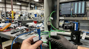
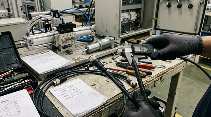
When you need to connect power to a solenoid valve, a small DC motor, or a pneumatic cylinder bank, you might reach for a standard M12 A-Code cable. But is the "sensor cable" in your stockroom the right choice for an actuator? Not always. While the M12 A-Code connector is versatile, the difference between a cable built for a low-power sensor and one built for a power-drawing actuator lies inside the jacket.
Using a cable with undersized wires for an actuator can lead to voltage drops, intermittent faults, and equipment underperformance. The key is to verify the cable's conductor size (wire gauge) against your actuator's current requirements.
Sensor vs. Actuator Cables: The Difference is Current
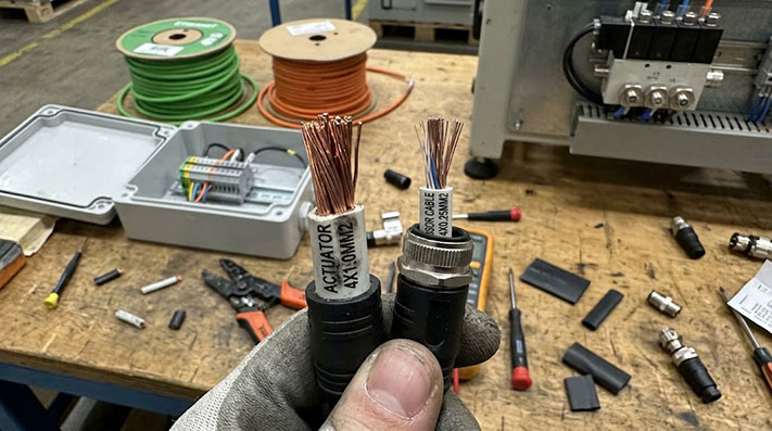
At a glance, an M12 A-Code sensor cable and an M12 A-Code actuator cable can look identical. They share the same physical connector, keying, and thread size. The critical distinction is not the connector itself, but the cross-sectional area of the copper conductors inside the cable.
-
Sensor Cables: These are designed to transmit low-energy signals. Proximity sensors, photoelectric sensors, and temperature probes typically operate on milliwatts of power. They send data, not force. For this purpose, thinner conductors (like 24 AWG or 0.25 mm²) are perfectly adequate and help keep the cable flexible and cost-effective.
-
Actuator Cables: These are designed to deliver operating power. Solenoid valves, small motor drives, electric grippers, and LED signal towers need a steady supply of current to function. This power delivery generates more heat and is more susceptible to voltage loss over distance. To handle this, actuator cables must use thicker conductors (such as 22 AWG, 20 AWG, or even 18 AWG) to carry the higher current safely and efficiently.
Using a thin-gauge sensor cable to power an actuator is a common cause of "mystery" machine faults.
M12 A-Code Pin-Count Electrical Ratings & Actuator Load Compatibility
| Pin Count & Layout | Max. Rated Voltage (IEC 61076-2-101) | Rated Current per Pin ($I_n$) | Contact Plating & Resistance ($R_c$) | Inrush Current Tolerance ($t < 10text{ms}$) | Target Actuator Applications |
|---|---|---|---|---|---|
| 3-Pin A-Code | 250 V AC / DC | 4.0 Amps | Gold over Nickel (≥0.8µm Au / ≤5 mΩ) | 12.0 Amps | Single Solenoid Valves, Pneumatic Cylinder Switches |
| 4-Pin A-Code | 250 V AC / DC | 4.0 Amps | Gold over Nickel (≥0.8µm Au / ≤5 mΩ) | 12.0 Amps | Double Solenoid Valves, Small DC Stepper Motors |
| 5-Pin A-Code | 60 V AC / DC | 4.0 Amps | Gold over Nickel (≥0.8µm Au / ≤5 mΩ) | 10.0 Amps | Smart Actuators with IO-Link, Pneumatic Manifolds |
| 8-Pin A-Code | 30 V AC / DC | 2.0 Amps | Gold over Nickel (≥0.4µm Au / ≤8 mΩ) | 5.0 Amps | Multi-channel LED Signal Towers, Compact Grippers |
| 12-Pin A-Code | 30 V AC / DC | 1.5 Amps | Gold over Nickel (≥0.4µm Au / ≤10 mΩ) | 3.0 Amps | Multi-I/O Junction Blocks, Vision Lighting Drives |
What Happens When You Use an Undersized Cable for an Actuator?
Connecting a power-hungry actuator with a cable designed for low-current signals creates immediate electrical problems. The undersized conductors have higher resistance, which chokes the flow of electricity and leads to several performance issues.
1. Voltage Drop and Weak Performance As current flows through the thin wires, the cable's resistance causes a significant drop in voltage. A 24VDC power supply might only deliver 22V or 21V to the actuator. This can cause:
- Solenoid valves to buzz, fail to open completely, or shift weakly.
- DC motors to run slower, with less torque than specified.
- Electric grippers to have reduced holding force.
Conductor Cross-Section, Current Capacity & Voltage Drop Matrix (24V DC Circuit)
| Conductor Gauge (AWG / mm²) | DC Resistance at 20°C ($R_{20}$) | Max Continuous Ampacity ($I_{text{max}}$ at 40°C) | Voltage Drop per Meter ($V_{text{drop}}/m$ at 1.5A Load) | Max Cable Length for 24V DC Valve ($V_{text{min}} ge 21.6text{V}$, 1.5A Load) | Thermal Rise ($Delta T$) under 2.0A Load |
|---|---|---|---|---|---|
| 26 AWG (0.14 mm²) | 138.0 Ω/km | 1.0 A (Sensor Spec) | 0.414 V / m | ≤ 5.8 meters | > +35°C (High Thermal Stress) |
| 24 AWG (0.25 mm²) | 79.0 Ω/km | 1.5 A | 0.237 V / m | ≤ 10.1 meters | +22°C |
| 22 AWG (0.34 mm²) | 52.0 Ω/km | 2.5 A (Standard Actuator) | 0.156 V / m | ≤ 15.3 meters | +12°C |
| 20 AWG (0.50 mm²) | 39.0 Ω/km | 3.5 A | 0.117 V / m | ≤ 20.5 meters | +7°C |
| 18 AWG (0.75 mm²) | 26.0 Ω/km | 4.0 A (M12 Pin Limit) | 0.078 V / m | ≤ 30.7 meters | +4°C (Cool & Stable) |
2. Overheating and Safety Risks Higher resistance creates heat. An undersized cable can become noticeably warm or even hot to the touch. Over time, this heat can degrade the wire's insulation and the outer cable jacket, making them brittle and increasing the risk of a short circuit. While not always an immediate fire hazard in low-voltage systems, it creates a point of failure and damages components.
3. Intermittent and Hard-to-Diagnose Faults The equipment might work correctly during setup but fail once it warms up or when multiple actuators are running simultaneously. These intermittent problems are frustrating to troubleshoot because the connection appears physically sound, but the electrical delivery is insufficient.
A Checklist for Specifying Your M12 Actuator Cable
To avoid these problems, treat the cable as a critical power delivery component, not just a connector. When preparing a drawing or RFQ, be ready to confirm these four points.
- Actuator Power Requirements: First, check the actuator's datasheet for its operating voltage (e.g., 24VDC) and, most importantly, its current draw (e.g., 0.5A, 1.2A). Note both the continuous and peak (inrush) current if available.
- Conductor Size (Wire Gauge): This is the single most important specification for an actuator cable. Based on the current draw and cable length, a specific wire gauge (AWG or mm²) is required. A lower AWG number means a thicker wire and higher current capacity. If you are unsure, provide the actuator's current draw to your supplier so they can recommend the correct gauge.
- Cable Length: Voltage drop increases with distance. A 10-meter cable will have a much larger voltage drop than a 1-meter cable with the same wire gauge. For long runs, you may need to specify an even thicker conductor to ensure the actuator receives its required voltage.
- Motion and Environment: Is the cable installed in a static cable tray or on a moving robotic arm? For dynamic applications, a cable with a PUR (polyurethane) jacket and a high flex rating is often necessary. If the area is exposed to oils or weld splatter, that also dictates the jacket material and construction.
Dynamic Mechanical Endurance & Environmental Resistance Matrix
| Cable Construction & Motion Class | Bending Radius Factor (Dynamic) | Conductor Stranding Spec (IEC 60228) | Tested Flexing / Torsional Life | Environmental Resistance Rating | Recommended Operational Environment |
|---|---|---|---|---|---|
| Flexible Stationary (PVC Jacket) | 10 × Cable OD | Class 5 Bare Copper (32×0.10mm) | ~100,000 Cycles | Basic IP67, Flame Retardant (UL VW-1) | Static cable trays, clean assembly enclosures |
| High-Flex Drag Chain (PUR Jacket) | 7.5 × Cable OD | Class 6 Extra-Fine Tinned (42×0.10mm) | ≥ 5,000,000 Cycles (at 3m/s²) | Free of Halogen, Resistant to Cutting Oils | CNC machining centers, high-speed pneumatic slides |
| Robotic Torsion 3D (PUR Spec) | 10 × Cable OD | Ultra-Fine Bundled (Ø 0.08mm) | ≥ 3,000,000 Cycles (at ±360°/m) | Oil, UV, Hydrolysis & Microbe resistant | 6-Axis Articulated Robots, End-of-Arm Tooling (EOAT) |
| Weld Slag Resistant (TPE/PUR-C) | 8 × Cable OD | Fine Tinned Copper | ≥ 5,000,000 Flex Cycles | Non-stick coating (Resists 1200°C spatter) | Automotive body-in-white welding cells, spot welding |
Outer Jacket Material Selection Guide for Actuator Applications
| Physical / Chemical Property | PVC (Polyvinyl Chloride) | PUR (Polyurethane) | TPE (Thermoplastic Elastomer) | Testing Standard |
|---|---|---|---|---|
| Operating Temperature (Flexing) | -5°C to +80°C | -25°C to +80°C | -40°C to +105°C | IEC 60811-501 |
| Resistance to Machine Coolants & Oils | Poor (Swells & hardens) | Superior (DIN EN 60811-404) | Exceptional | DIN EN 60811-404 |
| Halogen-Free (Zero Halogen) | No (Emits HCl gas when burned) | Yes (IEC 60754-1) | Yes (IEC 60754-1) | IEC 60754-1 / EN 50267 |
| Abrasion & Tear Resistance | Moderate | Ultra-High | High | DIN 53516 |
| Weld Slag / Hot Spark Immunity | Fail (Melts through) | Fair (Tack-free PUR variant available) | Superior (Cross-linked) | Internal Welding Test |
Getting the Right M12 A-Code Cable for Your Actuator
M12 A-code cable assemblies are a workhorse in industrial automation, suitable for both sensors and many actuators—as long as the cable is built for the job. Guessing about the wire gauge can lead to unreliable machine operation and hidden costs in troubleshooting and downtime.
When you send an RFQ for an actuator cable, don't just ask for an "M12 4-pin cable." Specify your actuator's voltage and current draw. This allows us to ensure the cable assembly is configured with the correct wire gauge. Providing details like the required cable length, jacket material, and a drawing or sample photo helps us build the exact solution you need, with no guesswork involved.