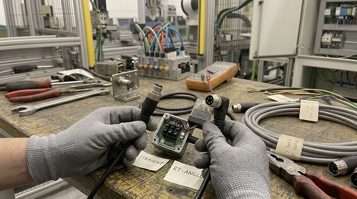
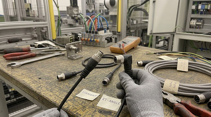
When selecting an M12 A-code sensor cable, one of the first decisions is choosing between a straight and a right-angle connector. While it seems simple, the wrong choice can lead to installation problems, cable strain, and premature failure.
The best choice depends entirely on the physical space around your sensor or connection port. Use a straight connector when you have ample clearance for the cable to exit without a sharp bend. Use a right-angle connector when space is limited, but be sure to account for both the connector’s height and the cable's own bend radius.
The Core Decision: Clearance and Cable Path
The main reason to choose a right-angle connector is to manage the cable path in a tight space. A straight connector requires a certain amount of unobstructed space directly in front of the port. A right-angle connector redirects the cable parallel to the mounting surface, significantly reducing the cable's protrusion from the equipment.
- Straight Connector Profile: The cable extends directly out from the port. This is ideal for open areas or when connecting to ports on a vertical panel where the cable can drop down naturally.
- Right-Angle Connector Profile: The cable exits at 90 degrees from the connector head. This is essential for mounting sensors in compact machine cells, near moving parts, or inside enclosures where a protruding cable could be snagged or damaged.
Electrical Ratings, Conductor Cross-Sections, and Impedance Limits
Compliant with IEC 61076-2-101. Pin count directly dictates conductor gauge constraints and maximum continuous current carrying capacity:
| Pin Count / Keying | Max. Wire Gauge (AWG / mm²) | Rated Voltage (IEC 60664-1) | Rated Current per Contact (at 40°C) | Impulse Voltage (1.2/50 µs) | Contact Resistance | Insulation Resistance |
|---|---|---|---|---|---|---|
| 3-Pin A-Code | 20 AWG (0.50 mm²) / 22 AWG | 250 V AC / DC | 4.0 A | 2,500 V | ≤ 5.0 mΩ | ≥ 100 MΩ |
| 4-Pin A-Code | 20 AWG (0.50 mm²) / 22 AWG | 250 V AC / DC | 4.0 A | 2,500 V | ≤ 5.0 mΩ | ≥ 100 MΩ |
| 5-Pin A-Code | 22 AWG (0.34 mm²) | 60 V AC / 60 V DC | 4.0 A | 1,500 V | ≤ 5.0 mΩ | ≥ 100 MΩ |
| 8-Pin A-Code | 24 AWG (0.25 mm²) | 30 V AC / 30 V DC | 2.0 A | 800 V | ≤ 8.0 mΩ | ≥ 100 MΩ |
| 12-Pin A-Code | 26 AWG (0.14 mm²) | 30 V AC / 30 V DC | 1.5 A | 500 V | ≤ 10.0 mΩ | ≥ 100 MΩ |
Key Measurements for Right-Angle Connectors
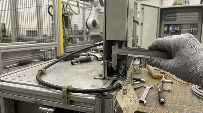
A "90-degree" connector isn't a magic solution for zero-clearance corners. You must account for the physical dimensions of the connector and the cable.
- Connector Body Height: The right-angle connector itself has a vertical profile. You must have enough clearance above the mounting port to accommodate the connector's overmolded head. This dimension can vary between manufacturers.
- Cable Exit Path: The cable does not make an instantaneous 90-degree turn. It exits the connector head and then begins its bend. The space required for the cable to bend without damage is its minimum bend radius. Forcing a tighter bend will stress the internal conductors and compromise the jacket.
- Orientation: A standard right-angle connector has a fixed cable exit direction relative to the connector's keyway. Ensure this orientation routes the cable away from obstacles, not into them.
Physical Envelope & Minimum Clearance Envelope Dimensions
To prevent interference with moving machine elements, use these nominal dimensions (based on IEC 61076-2-101 M12 A-Code molded assemblies) for CAD packaging checks:
| Connector Configuration | Protrusion Height from Panel (Mated) | Min. Cable Clearance (Outer Jacket Edge) | Total Clearance Required (inc. Min. Static Bend Radius) | Weight Vector / Mechanical Strain Direction |
|---|---|---|---|---|
| Straight Male / Female | 42.0 mm – 45.0 mm | N/A (Linear Exit) | 85.0 mm – 100.0 mm (Direct axial pull) | Pure axial tension / zero moment arm |
| Right-Angle (90°) Male / Female | 22.0 mm – 26.5 mm | 18.0 mm (Height from center line) | 35.0 mm – 40.0 mm (Saves >50% vertical envelope) | Radial torque / bending moment on M12 thread |
When is a Straight Connector a Better Choice?
Despite the space-saving benefits of right-angle plugs, straight connectors are often the default and preferred choice for several reasons:
- Accessibility: A straight connector is generally easier and faster to couple and uncouple by hand, especially if wearing gloves. The straight body provides a better grip.
- No Cable Stress: In applications with sufficient space, a straight cable run avoids creating a potential stress point at the connector exit.
- Simpler Cable Management: In open cable trays or long runs with gentle curves, straight connectors provide a clean and predictable cable path.
Motion Profile Constraints & Dynamic Cable Bending Specifications
Connecting sensors on moving robotic end-effectors or high-speed drag chains demands strict compliance with mechanical bending factors to prevent conductor shear:
| Mechanical Motion Parameter | Static / Fixed Installation | Dynamic Machine Flexing | Continuous Drag Chain Motion | High-Speed Robotic Torsion |
|---|---|---|---|---|
| Min. Bend Radius (Unshielded PUR) | 5 × Cable OD | 8 × Cable OD | 10 × Cable OD | 12 × Cable OD |
| Min. Bend Radius (Shielded / Braided) | 6 × Cable OD | 10 × Cable OD | 12 × Cable OD | 15 × Cable OD |
| Max. Cable Acceleration / Speed | N/A | 3.0 m/s² / 180 m/min | 50 m/s² / 300 m/min | Torsional angle ±360°/m |
| Flexing Life Cycles (PUR Outer Jacket) | N/A | > 2,000,000 cycles | > 5,000,000 to 10,000,000 cycles | > 3,000,000 cycles |
| Recommended Head Style | Straight or Right-Angle | Straight (with Strain Relief) | Straight Connector (Centered Strain) | Straight Connector Only (Right-Angle causes uneven moment arm under torsion) |
Overmolded Assemblies vs. Field-Wireable Connectors
Most M12 A-Code cables for production equipment are overmolded assemblies. The connector and cable are permanently joined at the factory, creating a sealed, durable unit that is less susceptible to moisture, dust, and vibration. This is the most reliable option for long-term performance.
Field-wireable connectors are separate components that you attach to a raw cable on-site. While they offer flexibility for repairs or custom lengths, they are more dependent on installer skill for a reliable connection and typically offer less robust environmental protection than a factory-molded assembly. For new designs and OEM applications, overmolded assemblies provide more consistent quality.
Signal Integrity, Shielding Topology, and Protocol Selection Matrix
A-Code cables support binary digital signals, analog measurements, and high-speed industrial point-to-point communications:
| Industrial Protocol / Signal Type | Shielding Construction | Shield Coverage (%) | Cable Impedance / Attenuation | Recommended Jacket & Conductor Type |
|---|---|---|---|---|
| Standard PNP/NPN Digital Discrete | Unshielded (UTP) | 0% | N/A | PVC or PUR / Twisted pairs optional |
| IO-Link (COM1 / COM2 / COM3) | Unshielded or Foil Shield (FTP) | ≥ 90% (Foil + Drain) | Standard ~100 Ω | PUR / Unshielded up to 20m per IEC 61131-9 |
| Analog Instrumentation (4-20mA / 0-10V) | 360° Tinned Copper Braid (STP) | ≥ 85% Braid Coverage | Low Capacitance (<60 pF/m) | Twisted Pairs with Drain Wire + PUR Jacket |
| RS-485 / Modbus RTU (A-Code 5-Pin) | Braid + Aluminum Foil Dual Shield | 100% Foil + 85% Braid | 120 Ω Nominal Impedance | Low-Loss Foam Polyethylene Insulation (PE) |
Preparing Your M12 Cable Specification
Whether you need straight, right-angle, or a combination, having clear requirements is key to getting the right part. A double-ended cable assembly can have a different connector style on each end (e.g., straight male to right-angle female) to meet specific equipment layouts.
Before sending an RFQ, gather the following details:
- Connector A: Male or Female? Straight or Right-Angle? Pin Count (e.g., 4-pin, 5-pin)?
- Connector B: Male or Female? Straight or Right-Angle? Or unterminated (pigtail)?
- Cable Length: Specify the required length in meters or millimeters.
- Application Environment: Note any tight spaces, vibration, moisture, or potential for physical impact. If you have a clearance measurement (e.g., "less than 50mm clearance above the port"), include it.
- Drawing or Photo: A simple sketch or a photo of the connection point is extremely helpful for clarifying complex requirements.
Installation Torque Specifications, Coupling Nut Materials, and IP Ingress Ratings
Proper seating of the internal FKM/NBR O-ring is crucial to prevent capillary water ingress under high-pressure cleaning or chemical spray:
| Mechanical / Sealing Parameter | Stainless Steel Nut (316L) | Nickel-Plated Brass Nut | Zinc Die-Cast / Plastic Nut |
|---|---|---|---|
| Recommended Tightening Torque | 0.6 Nm – 0.8 Nm (Use calibrated M12 torque wrench) | 0.6 Nm | 0.4 Nm – 0.5 Nm |
| Thread Locking Mechanism | Anti-vibration ratchet locking ring | Anti-vibration ratchet locking ring | Standard friction thread |
| Ingress Protection Rating (Mated) | IP67, IP68 (2m / 24h), IP69K (Washdown) | IP67, IP68 (1m / 24h) | IP65 / IP67 |
| O-Ring Gasket Material | FKM (Viton) / Fluorosilicone | NBR (Nitrile Rubber) | NBR |
| Operating Temperature Range | -40°C to +105°C | -25°C to +85°C | -10°C to +70°C |
Get the Right Configuration for Your Application
Choosing between a straight and right-angle M12 connector is a practical decision based on physical constraints. By measuring your clearance and considering the cable path, you can avoid installation issues and ensure a reliable connection.
If you are working with a tight space or a complex layout, provide us with your specifications. Let our team know the clearance you have around the port, and we can help you confirm the best connector angle or discuss a custom assembly design for your equipment.