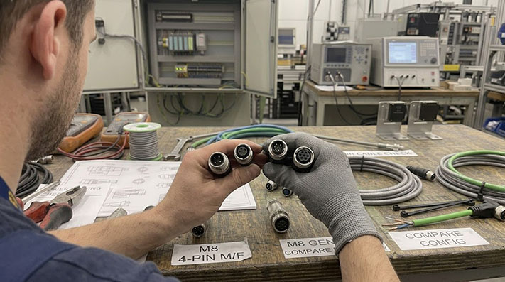
For a sourcing manager or automation systems integrator, reading a manufacturer datasheet for an M8 connector can feel like decoding a foreign dialect. Missing a single line item—such as the difference between A-coding and B-coding, or overlooking the difference between male and female face views—leads to misaligned pins, short circuits, or cables that fail prematurely in damp environment conditions.
This guide breaks down how to read an M8 datasheet line by line, mapping technical specifications directly to practical procurement and installation decisions.
Decoding the Technical Specifications Table
Every standard M8 datasheet contains an electrical and environmental specifications table. Below is a breakdown of what these figures mean for machine builders and MRO engineers.
| Datasheet Parameter | Typical M8 Specification | Practical Engineering Meaning |
|---|---|---|
| Rated Voltage | 30V AC/DC (4-Pin) to 60V AC/DC (3-Pin) | The absolute maximum continuous operating voltage. Running 120V or 230V mains power through a standard M8 sensor connector will bridge the insulation barrier and cause catastrophic failure. |
| Rated Current | 3A to 4A per contact | The current limit per pin. If a field actuator or solenoid valve pulls 4.5A, the pins will overheat, softening the plastic insert and causing open circuits. |
| Impulse Voltage | 800V to 1500V | The peak transient voltage spike the connector can withstand without dielectric breakdown (sparkover between pins). |
| Insulation Resistance | $ge 100text{ M}Omega$ | A measure of how well the plastic insert prevents current from leaking between conductors. High humidity or internal condensation drops this value. |
| Contact Resistance | $le 10text{ m}Omega$ | The electrical resistance at the mated pin-to-socket interface. High contact resistance indicates poor plating or loose physical tolerances, causing localized heating. |
| Ingress Protection (IP) | IP65, IP67, or IP68 | IP65: Splash-proof. IP67: Temporary immersion in water. IP68: Continuous immersion under specified pressures. Note that these ratings apply only when the connector is fully mated and correctly torqued. |
Contact Ratings, Wire Gauge (AWG), and Thermal Derating Specifications
Pin density directly impacts contact current capacity due to thermal dissipation constraints within the compact M8 housing.
| Pin Count | Standard Wire Gauge | Rated Current per Contact | Rated Voltage | Impulse Withstand Voltage | Ambient Operating Temperature Derating |
|---|---|---|---|---|---|
| 3-Pin | 24 AWG (0.25 mm²) | 4 A | 60 V AC/DC | 1.5 kV / 1 min | 100% rating up to 40°C; derate to 80% at 60°C; derate to 60% at 80°C |
| 4-Pin | 24 AWG (0.25 mm²) | 4 A | 30 V AC/DC | 0.8 kV / 1 min | 100% rating up to 40°C; derate to 80% at 60°C; derate to 60% at 80°C |
| 6-Pin | 26 AWG (0.14 mm²) | 1.5 A to 2 A | 30 V AC/DC | 0.8 kV / 1 min | Max. temperature rise ΔT < 30K at rated current |
| 8-Pin | 26 AWG (0.14 mm²) | 1.5 A | 30 V AC/DC | 0.8 kV / 1 min | High-density signal transmission; strictly low-power use |
Shielding Construction & EMC Noise Immunity Matrix
For high-precision analog sensors and high-speed signal lines, selecting the appropriate shield structure is critical to mitigate electromagnetic interference (EMI).
| Shielding Construction Type | Optical Coverage | Transfer Impedance | EMC Performance Grade | Optimal Application |
|---|---|---|---|---|
| Unshielded (UTP) | 0% | N/A | None | Standard discrete digital I/O (PNP/NPN switches) |
| Aluminum Foil (Al-Mylar Foil) | 100% | High frequency attenuation; prone to tear under flexing | Moderate | Static noise protection for high-frequency signals |
| Tinned Copper Braid | ≥ 85% | < 100 mΩ/m @ 30MHz | High | Dynamic drag chains, proximity to AC motor cables |
| Combination Foil + Tinned Copper Braid | 100% + 85% | < 10 mΩ/m @ 30MHz (Ultra-low impedance) | Very High (Industrial Premium) | Analog measuring sensors, high-interference VFD environments |
Pin Assignments for Common Sensor Types (Inductive, Photoelectric, Capacitive)
M8 datasheets reference pin numbers (typically 1 through 4, sometimes up to 8 for specialty high-density connectors). Industrial sensor manufacturers align these pins to specific wire colors and functions under the IEC 60947-5-2 standard.
When reviewing a datasheet for a sensor replacement cable, verify that the internal wire colors match this industrial standard.
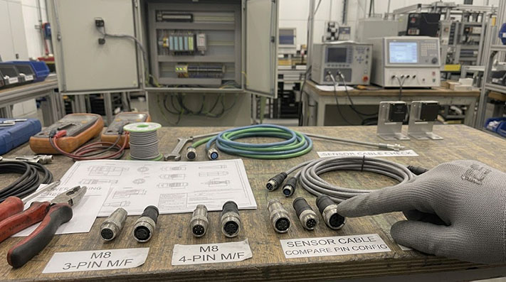
3-Pin M8 Sensor Configuration
The 3-pin configuration is the baseline standard for basic proximity switches and inductive sensors.
- Pin 1 (Brown): +24V DC Power Supply (VCC)
- Pin 3 (Blue): 0V DC / Ground (GND)
- Pin 4 (Black): Switching Output (usually PNP or NPN, Normally Open)
4-Pin M8 Sensor Configuration
The 4-pin configuration is common in photoelectric, ultrasonic, and capacitive sensors where a secondary control signal or diagnostic output is required.
- Pin 1 (Brown): +24V DC Power Supply (VCC)
- Pin 2 (White): Second Output or Input (often used for Teach-in, Light/Dark operate selection, or a secondary Normally Closed output)
- Pin 3 (Blue): 0V DC / Ground (GND)
- Pin 4 (Black): Primary Switching Output (Normally Open)
If your system uses 3-pin sensors but your wiring inventory consists of 4-pin female M8 cables, you can typically use the 4-pin cable as a replacement. Pin 2 (the white wire) will simply remain disconnected in the junction box or PLC terminal strip.
Male vs. Female Field-Side: The Convention That Trips Up Beginners
One of the most frequent errors in connector procurement is ordering the incorrect gender for the field-side cable. This confusion stems from how connector pins and sockets are arranged relative to the power supply.
The Safety Standard
In industrial automation, live power must always flow from a female connector (socket contacts) to a male connector (pin contacts). This ensures that if a cable is disconnected while energized, the live contacts remain recessed inside the insulated female plastic body, preventing accidental human contact or shorting against the machine frame.
- Sensors and Actuators (Power Consumers): These devices almost always feature an integrated M8 Male receptacle (pins exposed on the device housing).
- Sensor Cables (Power Carriers): The cable connecting to the sensor must have an M8 Female connector on the device end.
- Distribution Blocks / PLC Input Cards: These power-distribution units feature M8 Female ports. The controller-end of the cable will therefore require an M8 Male connector if it is a double-ended cordset.
The Mirror-Image Viewing Trap
When looking at the pin assignment drawings on a datasheet, pay close attention to the perspective.
- A male face view shows the pins pointing toward your eye. The numbering typically runs clockwise.
- A female face view shows the sockets pointing toward your eye. The numbering runs counter-clockwise.
Always cross-reference the pin configuration diagrams to ensure you are looking at the mating face rather than the rear solder/wire termination side of the connector.
Cable Gland vs. Molded: Serviceability Trade-offs
Datasheets list the housing type as either "molded" (overmolded cordset) or "field-wireable" (cable gland/shell assembly). Sourcing managers must balance assembly time against long-term maintenance costs when choosing between these two designs.
Mechanical & Cable Life Performance in Dynamic Drag Chain Applications
In automated machinery, mechanical stress directly affects sensor cable reliability. Physical performance parameters must be specified based on the motion profile to prevent conductor fatigue and premature open circuits.
| Evaluation Metric / Parameter | Fixed Installation | Flexible Installation | Continuous Drag Chain Application | Torsional Robotic Application |
|---|---|---|---|---|
| Min. Bending Radius | 5 × Outer Diameter (OD) | 7.5 × OD | 10 × OD | 10 × OD |
| Bending Cycles | N/A | ~1,000,000 cycles | ≥ 5,000,000 to 10,000,000 cycles | ≥ 2,000,000 cycles |
| Max. Acceleration / Speed | N/A | 5 m/s² / 180 m/min | 50 m/s² / 300 m/min | 180°/m torsional angle |
| Recommended Conductor Stranding | Class 2 or Class 5 | Class 5 (fine stranded copper) | Class 6 (extra-fine bare/tinned copper, single wire Ø ≤0.1mm) | Class 6 extra-fine bundled stranding |
Cable Jacket Material Selection Matrix for Industrial Environments
Selecting the correct jacket material ensures long-term chemical and environmental compatibility on the factory floor.
| Jacket Material | PUR (Polyurethane) | PVC (Polyvinyl Chloride) | TPE (Thermoplastic Elastomer) |
|---|---|---|---|
| Operating Temperature Range | -40°C to +90°C | -20°C to +80°C | -50°C to +105°C |
| Coolant / Industrial Oil Resistance | Excellent (UL 1581 / DIN EN 60811-404) | Moderate | Excellent |
| Abrasion / Tear Resistance | Very High | Low | High |
| Flame Retardancy Grade | UL 94-V0, FT2 | UL 94-V2, FT1 | UL 94-V0, FT1/FT2 |
| Halogen-Free (LSZH) | Yes (IEC 60754-1) | No (contains chlorine) | Yes |
| Optimal Target Application | CNC machine tools, drag chains, harsh oily environments | Dry, low-stress fixed cabinet wiring | Extreme cold / high-flexibility robotic automation |
Mechanical Sealing & Field Torque Installation Specifications
Achieving long-term IP ratings and vibration resistance requires adhering to explicit mechanical torque parameters during field assembly.
| Specification Parameter | Standard Value / Grade | Engineering Control Point |
|---|---|---|
| Ingress Protection (IP Rating) | IP65 / IP67 / IP68 (2m / 24h) / IP69K | IP69K requires resistance to 80°C, 100 bar high-pressure washdown |
| Recommended Coupling Nut Torque | 0.4 Nm – 0.6 Nm (Use calibrated M8 torque wrench) | Under-torquing compromises O-ring sealing; over-torquing strips plastic threads |
| Mating Cycles / Contact Durability | ≥ 100 cycles | Compliant with IEC 61076-2-104 gold-plated contact standards (Au thickness ≥0.8µm) |
| Vibration & Shock Resistance | 10–2000 Hz at 10g (IEC 60512-6-4) | Ensures anti-vibration ratcheting mechanism prevents loosening on dynamic axes |