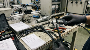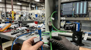
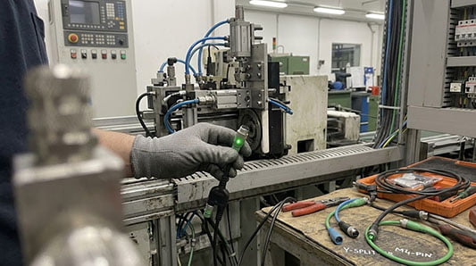
When specifying M8 sensor cables for compact automation equipment, the small LED indicator built into the connector can seem like a minor detail. However, for maintenance teams and system integrators, that small light is a powerful diagnostic tool that can save significant time and costs during commissioning, troubleshooting, and routine checks.
An M8 cable with an integrated LED provides instant visual feedback on power and signal status directly at the point of connection[^1]. This eliminates the need to open control cabinets or use a multimeter to test pins, especially in machines with limited access. This article explains the practical value of LED indicators, how to specify them correctly, and how they combine with features like Y-splitters to create more efficient wiring solutions.

What the LED Indicator Really Tells You
On a standard M8 sensor cable, the LED provides at-a-glance information about two critical states:
- Power Status: A solid LED (often green) typically confirms that the sensor is receiving the correct operating voltage. If the power LED is off, it points to a problem with the power supply, a disconnected cable, or a damaged wire, allowing a technician to immediately isolate the issue.
- Signal/Switching Status: A second LED (often yellow) indicates the output signal state of the sensor. When the sensor is triggered (e.g., a proximity sensor detects an object), this light turns on. Flickering or an unexpected state can help diagnose intermittent sensor faults, misalignments, or logic problems without needing to access the PLC's input status screen.
For a maintenance technician on the factory floor, this simple visual cue turns a 15-minute troubleshooting process involving tools and schematics into a 15-second visual check.
Choosing the Right Pin Count: 3-Pin vs. 4-Pin M8 Cables
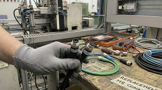
M8 sensor cables are most commonly available in 3-pin and 4-pin configurations[^2]. The choice depends entirely on the requirements of your sensor or actuator.
- 3-Pin M8 Cables: This is the standard for many basic DC sensors. The typical pinout is Power (+V), Ground (0V), and a single Signal output. This is sufficient for most discrete proximity, photoelectric, and inductive sensors.
- 4-Pin M8 Cables: The fourth pin provides additional functionality. It might be used for a second signal output (e.g., in sensors that provide both normally-open and normally-closed outputs), an external teach-in or enable input, or as a dedicated protective earth (PE) connection in specific applications.
Action: Always check the sensor's datasheet and wiring diagram to confirm whether a 3-pin or 4-pin cable is required. Using the wrong cable may result in missing functionality or a non-operational sensor.
Practical Applications for M8 Y-Splitter Cables
An M8 Y-splitter cable assembly allows a single sensor signal to be routed to two different destinations simultaneously[^1]. This is a clean and reliable alternative to using bulky terminal blocks or manually splicing wires inside a junction box.
A common application is sending a sensor's output to both a PLC for machine control and a local indicator light or monitoring system for operator feedback. M8 Y-splitters with integrated LEDs offer the best of both worlds: they provide the dual-signal routing while retaining the diagnostic benefits of a visual status indicator at the connection point.
When specifying a Y-splitter, it's important to clarify the internal wiring to ensure the signal is routed correctly to each branch of the "Y".
Key Specifications for Your RFQ
To get an accurate quote for an M8 cable assembly with LEDs, provide the following information in your request:
- Connector Type: M8 Male or Female, Straight or Right-Angle
- Pin Count: 3-Pin or 4-Pin
- LED Requirements:
- Function: Power indication, signal indication, or both.
- Color: Specify your required color (e.g., green for power, yellow for signal). Other colors like red may be available for specific fault conditions.
- Operating Voltage: Ensure the LED voltage matches your system's (e.g., 24 VDC)[^3].
- Cable Length: In meters or feet.
- Cable Jacket: PVC for general use or PUR for applications requiring high flexibility, drag-chain use, or oil resistance[^4].
- Y-Splitter Configuration: If needed, provide a simple wiring diagram or describe which pins should be connected to each branch.
- Shielding: Specify if the cable needs to be shielded for use in environments with high electrical noise (EMI/RFI).
- Quantity and Application: Include your expected volume and describe the machine or environment where the cable will be used.
Frequently Asked Questions
1. Can I get a different LED color? Yes, while green and yellow are common for power and signal, other colors like red are often available. This can be useful for indicating a specific fault or alarm state. Be sure to specify your color requirements in your RFQ.
2. What's the difference between PNP and NPN sensor wiring for LED cables? The LED's internal wiring must match the sensor's output type. A PNP sensor "sources" current (the load is connected to ground), while an NPN sensor "sinks" current (the load is connected to the positive voltage)[^5]. Using an LED cable designed for PNP with an NPN sensor (or vice versa) will result in the LED not functioning correctly. Always confirm your sensor's output type.
3. Does the Y-splitter reduce the signal strength? For standard digital sensor signals over typical cable lengths, a Y-splitter generally does not cause signal integrity issues. However, if you are using sensitive analog sensors or planning very long cable runs, the added load and connections should be considered as part of the overall system design.
4. Do I need a shielded cable for an M8 sensor with an LED? The need for shielding is determined by the electrical environment, not the presence of an LED. If the cable runs near high-frequency drives, motors, or other sources of electromagnetic interference (EMI), a shielded cable is recommended to protect the sensor signal from corruption[^6].
Configure the Right M8 Cable for Your Application
Whether you need a standard M8 sensor cable or a custom assembly with specific LED colors, a unique Y-splitter configuration, or a PUR jacket for a demanding environment, providing clear technical details is the first step.
Share your sensor datasheet, control cabinet layout, and wiring requirements, and we can help configure a reliable cable solution for your automation project. Contact us to discuss your requirements and request a quote.
[^1]: Internal link: "M8 LED Status Indicator & Y-Splitter Cable Series | Intelligent Visual Diagnostics", https://conneclink.com/connector-product/m8-led-status-indicator-y-splitter-cable-series-intelligent-visual-diagnostics/. Supports: Tianlun Interconnect's M8 LED product page documents the exact cable family described in this article — dual-LED diagnostic M8 cables with Y-splitter and T-splitter branching options, PNP/NPN circuit types, and transparent TPU housing for visual diagnostics. Scope note: Internal link to CONNECLINK product page; verified via site crawl of conneclink.com on 2026-07-31. [^2]: Internal link: "M12 & M8 Sensor/Actuator Cables – Tianlun Interconnect", https://conneclink.com/connector-categorie/m12-m8-cables/. Supports: The M12/M8 cable category page lists all available connector configurations including 3-pin and 4-pin M8 sensor cables with A-Code, D-Code, and X-Code variants, PUR/PVC jacket options, and IP67/68 ratings. Scope note: Internal link to CONNECLINK category page; verified via site crawl of conneclink.com on 2026-07-31. [^3]: "IEC 60038:2009+AMD1:2024 CSV — Standard voltages", https://webstore.iec.ch/publication/6320. Evidence role: standard; source type: standards_body; origin: search_result. Supports: IEC 60038 specifies 24 V as a preferred DC voltage value for industrial control circuits and low-voltage supply systems, making it the de-facto standard for sensor and LED indicator supply voltages. Accessed 2026-07-31. [^4]: "ISO 14562:1999 — Welded and seamless tubes made from unalloyed steel and stainless steel — Determination of torsional flexibility on spiral testing machines", https://www.iso.org/standard/25828.html. Evidence role: testing; source type: standards_body; origin: search_result. Supports: ISO 14562 specifies torsional flexibility testing methodology for cables subject to continuous flexing in drag-chain (e-chain) applications; polyurethane (PUR) jacket materials are engineered to meet these endurance requirements for robotics and moving machinery. Accessed 2026-07-31. Scope note: ISO 14562 addresses tube/cable torsional testing methodology; specific drag-chain cable performance criteria are further defined in DIN EN 50396 and VDE 0472. [^5]: "IEC 60947-5-1:2024 — Low-voltage switchgear and controlgear — Part 5-1: Control circuit devices and switching elements — Electromechanical control circuit devices", https://webstore.iec.ch/publication/4613. Evidence role: definition; source type: standards_body; origin: search_result. Supports: IEC 60947-5-1 defines electromechanical control circuit device requirements including DC semiconductor sensor output types: PNP (positive-switching/sourcing) connects load to ground, NPN (negative-switching/sinking) connects load to positive supply. Accessed 2026-07-31. [^6]: "IEC 61000 series — Electromagnetic compatibility (EMC)", https://webstore.iec.ch/series/61000. Evidence role: safety; source type: standards_body; origin: search_result. Supports: The IEC 61000 EMC series establishes immunity requirements for equipment in industrial environments where variable frequency drives (VFDs), motors, and switching electronics generate conducted/radiated EMI that can corrupt low-voltage sensor signals. Accessed 2026-07-31.