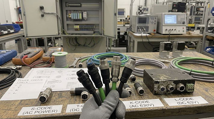
M12 connectors are no longer restricted to low-voltage sensor signals. With the introduction of the IEC 61076-2-111 standard, M12 power cables have become the standard for compact power transmission in decentralized automation. However, specifying these cables introduces a critical challenge: choosing between S, T, K, and L codings.
Selecting the wrong coding can lead to equipment damage, safety violations, or physical incompatibility on the factory floor. This guide details the electrical, physical, and practical differences between these four power codings to ensure you match the correct cable to your application.
Direct Selection Summary
If you need a quick decision path based on your system's power supply requirements:
- For high-voltage AC applications (up to 630V AC, e.g., small motors, pumps): Select S-Code (3-phase) or K-Code (3-phase with an extra pin for auxiliary power or grounding).
- For low-voltage DC applications (up to 63V DC, e.g., fieldbus I/O, control circuits): Select T-Code (up to 12A) or L-Code (up to 16A, recommended for PROFINET devices).
Mechanical & Cable Life Performance in Dynamic Applications
In automated environments, physical durability dictates cable service life. Mechanical performance parameters must be aligned with motion profiles (fixed, continuous flexing, or torsional robotic movement) to prevent conductor fatigue and jacket abrasion.
| Evaluation Metric / Parameter | Fixed Installation | Flexible Installation | Continuous Drag Chain Application | Torsional Robotic Application |
|---|---|---|---|---|
| Min. Bending Radius | 5 × Outer Diameter (OD) | 7.5 × OD | 10 × OD | 10 × OD |
| Bending Cycles | N/A | ~1,000,000 cycles | ≥ 5,000,000 to 10,000,000 cycles | ≥ 2,000,000 cycles |
| Max. Acceleration / Speed | N/A | 5 m/s² / 180 m/min | 50 m/s² / 300 m/min | 180°/m torsional angle |
| Recommended Conductor Stranding | Class 2 or Class 5 | Class 5 (fine stranded copper) | Class 6 (extra-fine bare/tinned copper, single wire Ø ≤0.1mm) | Class 6 extra-fine bundled stranding |
Voltage and Current Ratings Per Coding Type
The primary distinction among M12 power codings is their electrical capacity. Standard M12 signal connectors (typically A-coded) are limited to small currents (usually 2A to 4A) and low voltages. M12 power connectors utilize thicker conductors (typically 1.5 mm² to 2.5 mm² or 16 AWG to 14 AWG) and specialized contact designs to handle significantly higher thermal and electrical loads.
The table below outlines the nominal limits defined under the IEC 61076-2-111 standard.
| Coding Type | Power Type | Max Voltage | Max Current | Typical Pin Configuration | Primary Grounding/Functional Earth |
|---|---|---|---|---|---|
| S-Code | AC | 630 V AC | 12 A | 2+PE, 3+PE | Protective Earth (PE) contact |
| T-Code | DC | 63 V DC | 12 A | 4-pin | None (or Functional Earth on outer ring) |
| K-Code | AC | 630 V AC | 12 A / 16 A | 4+PE | Protective Earth (PE) contact |
| L-Code | DC | 63 V DC | 16 A | 4-pin, 4+FE | Functional Earth (FE) contact |
Note: Always verify the specific manufacturer's engineering datasheet, as actual operational ratings can be lower depending on the cable jacket material, ambient operating temperature, and wire gauge (AWG) used in the assembly.
Cable Jacket Material Selection Matrix
Selecting the appropriate jacket compound is vital for long-term reliability in industrial environments with exposure to cutting fluids, extreme temperatures, or mechanical wear.
| Jacket Material | PUR (Polyurethane) | PVC (Polyvinyl Chloride) | TPE (Thermoplastic Elastomer) |
|---|---|---|---|
| Operating Temperature Range | -40°C to +90°C | -20°C to +80°C | -50°C to +105°C |
| Industrial Coolant / Oil Resistance | Excellent (UL 1581 / DIN EN 60811-404) | Moderate | Excellent |
| Abrasion / Tear Resistance | Very High | Low | High |
| Flame Retardancy | UL 94-V0, FT2 | UL 94-V2, FT1 | UL 94-V0, FT1/FT2 |
| Halogen-Free (LSZH) | Yes (IEC 60754-1) | No (contains chlorine) | Yes |
| Typical Target Application | Machine tools, drag chains, cutting oil environments | Dry, low-stress fixed cabinet wiring | Extreme cold / ultra-flexible robotic applications |
Advanced Electrical & Thermal Derating Specifications
Standard ratings apply at reference temperatures (typically 20°C to 40°C). Operating at higher ambient temperatures requires applying thermal derating factors to preserve conductor insulation integrity and contact conductivity.
| Coding Type | Wire Gauge (AWG / mm²) | Impulse Voltage / Dielectric Withstand | Insulation Resistance | Contact Resistance | Ambient Temperature Derating Factor |
|---|---|---|---|---|---|
| S-Code | 1.5 mm² (16 AWG) / 2.5 mm² (14 AWG) | 1.5 kV AC / 1 min | ≥ 100 MΩ | ≤ 5 mΩ | 100% rating at 40°C; derate to 80% at 60°C; derate to 60% at 80°C |
| T-Code | 1.5 mm² (16 AWG) | 0.8 kV DC / 1 min | ≥ 100 MΩ | ≤ 5 mΩ | 12A at 40°C; reduce to <8A above 70°C |
| K-Code | 2.5 mm² (14 AWG) | 1.5 kV AC / 1 min | ≥ 100 MΩ | ≤ 3 mΩ | Designed to maintain temperature rise ΔT < 30K under high power |
| L-Code | 2.5 mm² (14 AWG) | 0.8 kV DC / 1 min | ≥ 100 MΩ | ≤ 3 mΩ | FE (Functional Earth) pin feature: dedicated low-impedance path (<2 mΩ) |
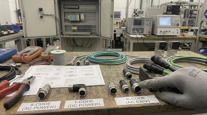
Real-World Use Cases: VFDs, Motors, and Power Distribution Blocks
To prevent selection errors, match your equipment's power design to the correct coding. Below are typical application profiles for each coding option.
S-Code Application Profile: AC Motors and Pumps
- Target Equipment: Small three-phase AC motors, water pumps, fans, and frequency converters (VFDs).
- Why S-Code: Three-phase AC machinery requires a dedicated Protective Earth (PE) contact that makes contact first and breaks last during mating. The S-Code provides this physical safety grounding path alongside three power conductors, allowing it to safely distribute up to 630V AC.
T-Code Application Profile: Auxiliary DC Power and Fieldbus Nodes
- Target Equipment: Network switches, distributed I/O blocks, and auxiliary power circuits.
- Why T-Code: Before the adoption of L-coding, T-code was the primary solution for supplying up to 12A of DC power to fieldbus systems. It remains widely used in legacy automation installations to power standard 24V DC devices without requiring bulky terminal boxes.
K-Code Application Profile: High-Power AC Drives and Distribution Blocks
- Target Equipment: Compact AC servo drives, multi-phase power distribution manifolds, and heavy-duty AC power supplies.
- Why K-Code: Similar to S-Code but with an extra contact pin (4+PE). This 5-pin design allows integrators to run three-phase AC power plus an auxiliary signaling or control line through a single space-saving M12 interface, reducing overall cabling footprint on complex machinery.
L-Code Application Profile: PROFINET and High-Current DC I/O Systems
- Target Equipment: PROFINET-managed I/O modules, machine vision systems, and high-draw DC distribution boxes.
- Why L-Code: The L-code is officially recommended by PI (PROFIBUS & PROFINET International) as the standard power interface for PROFINET devices. Its 16A capacity provides a 33% increase in power delivery over T-code at 24V DC, enabling engineers to daisy-chain multiple I/O blocks together off a single power run.
Shielding Structure & EMC Performance Matrix
Variable Frequency Drives (VFDs) and AC servo drives generate substantial high-frequency electromagnetic interference (EMI). Implementing proper shield construction is essential to safeguard adjacent sensitive signal and communication lines.
| Shielding Construction | Optical Coverage | Transfer Impedance | EMC Performance Grade | Optimal Application |
|---|---|---|---|---|
| Aluminum Foil (Al-Mylar Foil) | 100% | Effective for high frequency, but susceptible to tearing under flexing | Low | Static installation / high-frequency noise protection |
| Tinned Copper Braid | ≥ 85% | < 100 mΩ/m @ 30MHz | High | Dynamic drag chain applications, high-current AC power |
| Combination Foil + Tinned Copper Braid | 100% + 85% | < 10 mΩ/m @ 30MHz (Ultra-low impedance) | Very High (Industrial Premium) | VFD drive output, servo motors with high EMI risks |
Hot-Swap Safety: Why You Never Mix Up Power Codings
Using the incorrect connector coding on an assembly line poses a severe electrical hazard. If an operator accidentally connects a high-voltage AC power source to a low-voltage DC control board, the resulting overvoltage will instantly destroy downstream components and can cause arc flashes or electrical fires.
To eliminate this human error, the M12 power standard relies on mechanical keying.
Mechanical Sealing & Torque Installation Specifications
Achieving reliable long-term IP protection and preventing pin thermal oxidation requires strict adherence to mechanical mating specifications during field installation.
| Specification Parameter | Standard Value / Grade | Engineering Control Point |
|---|---|---|
| Ingress Protection Rating | IP67 / IP68 (2m / 24h) / IP69K | IP69K requires resistance to 80°C, 100 bar high-pressure washdown |
| Recommended Tightening Torque | 0.6 Nm – 1.0 Nm (Use calibrated torque wrench) | Under-torquing leads to seal integrity failure; over-torquing damages O-rings / plastic threads |
| Mating Cycles / Mechanical Life | ≥ 100 cycles | Compliant with IEC 61076-2-111 gold-plated contact requirements (thickness ≥0.8µm Au) |
| Flame Retardance & Fire Safety | VW-1 / IEC 60332-1-2 | Ensures flame propagation prevention along cable runs during short-circuit events |